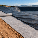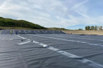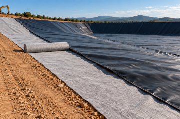

The default choice for a wastewater lagoon is an HDPE geomembrane at 60 mil, or 1.52 mm, while a clear water pond drops to 30 mil, or 0.76 mm. [1]
Where the subgrade settles unevenly or freezes and thaws, LLDPE takes over at 800 percent elongation against 700 percent for HDPE, at the cost of 23 percent less puncture resistance at the same gauge, 370 N against 480 N at 1.5 mm. [2][3]
GCL and compacted clay are the two non-membrane routes, and both suit ponds with no industrial constituents.
Gauge comes off head and puncture. One metre of water is 9.81 kPa, which puts 25 to 44 kPa on an anaerobic lagoon floor and 20 to 59 kPa on a mechanically aerated one. [4]
That 60 mil figure is the wastewater floor. Floor gravel over 20 mm, aerator supports or repeated wheel loads during cleanout push it to 80 mil. [1]
One liner or two is a regulatory question. 40 CFR 264.221(a) asks for one liner on a hazardous waste surface impoundment that (c) does not cover. [5]
New and expanded units fall under (c) and take two or more liners with leachate collection and removal between them, while (b) is the case-by-case exemption. [5]
Under the upper liner, at least 91 cm of compacted soil holds permeability at no more than 1 x 10⁻⁷ cm/s, or 1 x 10⁻⁹ m/s, and the leak detection layer takes a 1 percent slope, or 10 mm of fall per metre. [5]
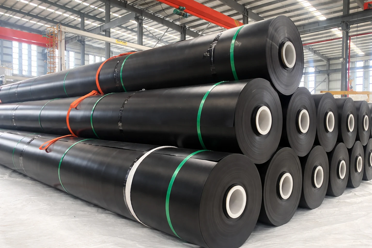
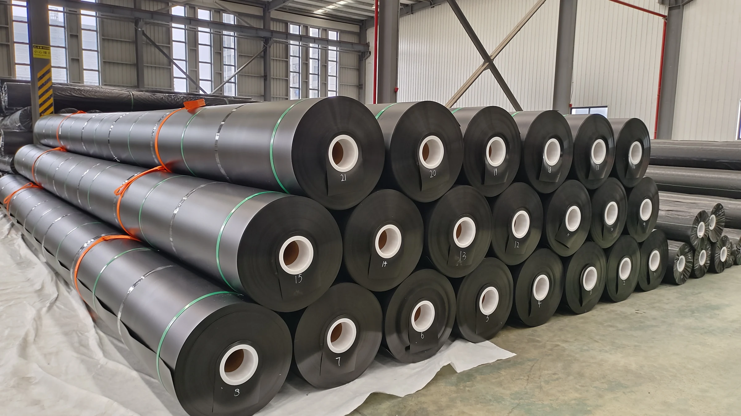
One 1.5 mm HDPE roll measures 8 m wide by 140 m long, covers 1,120 m² and weighs 1.58 t. A 10,000 m² floor with 10 percent waste allowance takes 10 rolls, about 16 t.
Pond type sets the head
| Pond type | Depth m | Detention | Main effect on the liner |
|---|---|---|---|
| Anaerobic | 2.5–4.5 | 5–50 days | No dissolved oxygen, highest hydrogen sulphide and organic acid load of the four |
| Mechanically aerated | 2–6 | 3–10 days | Aerators keep the surface moving, so the liner takes repeated scour |
| Facultative | 0.9–2.4 | 5–50 days warm, 90–180 days cold | Low head, membrane exposed for its whole service life |
| Aerobic | 0.3–0.45 | 2–6 days | Shallow, so it spreads the most membrane per unit of volume |
Working depth of 4.5 m at 1,000 m³ a day over 135 days needs 135,000 m³ of storage on a 30,000 m² floor.
That floor measures 173 m a side and 692 m around. With 4.5 m of depth on a 2-to-1 slope each side develops 10.1 m of slant, so the slopes add 7,000 m² and the membrane laid covers about 37,000 m².
Which membrane
HDPE geomembrane carries a density floor of 0.940 g/cm³, or 940 kg/m³. Stress crack resistance has to hold 500 hours. [3][6]
LLDPE carries a density ceiling of 0.939 g/cm³, 0.1 percent away from HDPE, and tonnage on a 10,000 m² floor differs by under 1 percent. [2][3]
The 500 hours come from GRI-GM10, which sets the SP-NCTL bar at 4 of 5 specimens failing above 500 hours and the last one above 250 hours. [7][6]
A 91 cm compacted clay layer seeps 0.76 cm/d after a year under 6 m of head, against 0.003 cm/d for a 1.1 mm synthetic membrane, about 250 times less. GCL holds water with 3.66 kg/m² of bentonite, so that choice against compacted clay comes down to hydraulic conductivity against installation cost. [1][4]
| Item | HDPE membrane | LLDPE membrane | GCL | Compacted clay |
|---|---|---|---|---|
| Governing specification | GRI-GM13 | GRI-GM17 | NRCS 521 | NRCS 521 |
| Gauge or dosage | 0.75–3.00 mm, no less than 60 mil for wastewater | 0.50–3.00 mm, no less than 60 mil for wastewater | Bentonite no less than 0.75 lb/ft² | Layer no less than 91 cm |
| Density or permeability | No less than 0.940 g/cm³ | No more than 0.939 g/cm³ | Index flux by D5887 | No more than 1×10⁻⁷ cm/s |
| Tensile at break, 1.5 mm | 40 kN/m | 40 kN/m | Judged on peel strength | Not applicable |
| Elongation at break | 700% | 800% | Not applicable | Not applicable |
| Puncture D4833, 1.5 mm | 480 N | 370 N | Not applicable | Not applicable |
| Stress crack resistance D5397 | No less than 500 h | Not listed | Not applicable | Not applicable |
| Carbon black D4218 | 2.0–3.0% | 2.0–3.0% | Not applicable | Not applicable |
| Liner | Thickness | Seepage cm/d | Seepage L/(m²·d) | Loss on 10,000 m² m³/d |
|---|---|---|---|---|
| Bare sand and gravel | n/a | 244 | 2,440 | 24,400 |
| Loose earth | n/a | 122 | 1,220 | 12,200 |
| Chemically treated loose earth | n/a | 30.5 | 305 | 3,050 |
| Bentonite-treated loose earth | n/a | 25.4 | 254 | 2,540 |
| Earth in cut | n/a | 30.5 | 305 | 3,050 |
| Soil cement | 10.2 cm | 10.2 | 102 | 1,020 |
| Gunite | 3.8 cm | 7.6 | 76 | 760 |
| Asphalt concrete | 10.2 cm | 3.8 | 38 | 380 |
| Un-reinforced concrete | 10.2 cm | 3.8 | 38 | 380 |
| Compacted earth | 91 cm | 0.76 | 7.6 | 76 |
| Prefabricated asphalt panels | 1.3 cm | 0.08 | 0.8 | 8 |
| Synthetic membrane | 1.1 mm | 0.003 | 0.03 | 0.3 |
Which gauge
Gauge comes off the D4833 index puncture value and a large-scale hydrostatic puncture to D5514, and thickness conversion covers the whole 1.0 to 3.0 mm range. Stepping from 60 mil to 80 mil adds 0.47 kg/m² and 4.7 t across 10,000 m². [9]
| Nominal mm | Trade mil | Lowest of 10 mm | Puncture N | Puncture lb | Yield kN/m | Tear N |
|---|---|---|---|---|---|---|
| 0.75 | 30 | 0.675 | 240 | 54 | 11 | 93 |
| 1.00 | 40 | 0.90 | 320 | 72 | 15 | 125 |
| 1.50 | 60 | 1.35 | 480 | 108 | 22 | 187 |
| 2.00 | 80 | 1.80 | 640 | 144 | 29 | 249 |
| 2.50 | 100 | 2.25 | 800 | 180 | 37 | 311 |
| 3.00 | 120 | 2.70 | 960 | 216 | 44 | 374 |
A nominal 1.5 mm sheet converts to 59.1 mil exactly, while the trade still writes 60 mil. GRI-GM13 lets the lowest of 10 thickness readings fall 10 percent under nominal, and our own release window holds minus 3 percent on those same 10 readings, or 0.105 mm at 1.5 mm. [3]
Smooth or textured
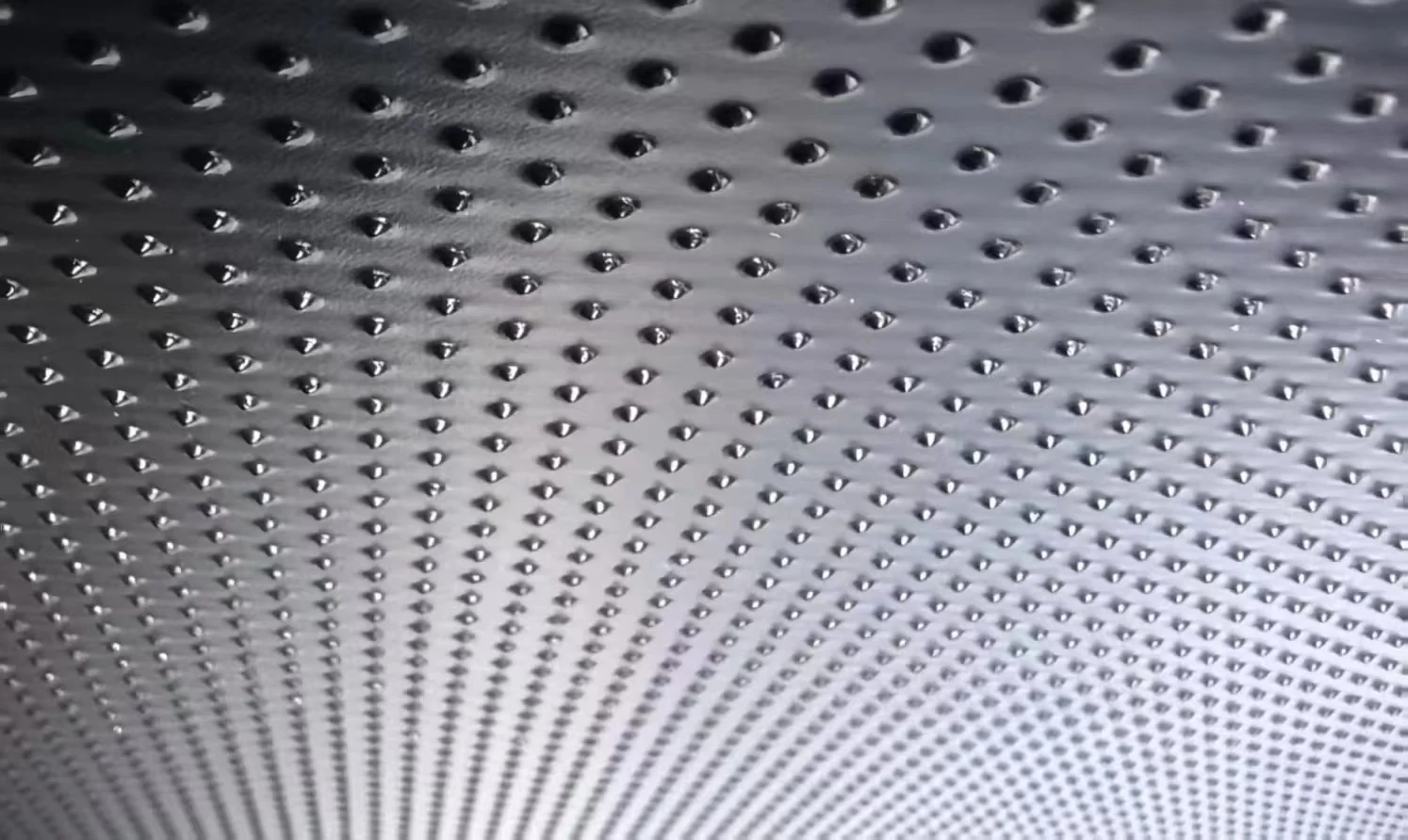
Textured sheet has an asperity height floor of 16 mil, or 0.41 mm, measured to ASTM D7466. Slopes up to 18.4 degrees, or 3-to-1, take smooth sheet over geotextile, and anything above 26.6 degrees, or 2-to-1, takes textured sheet. [13][14]
Cover soil that has to stay put needs an interface friction coefficient of at least 0.50 on a 2-to-1 slope and 0.33 on 3-to-1. [13]
That value comes from an ASTM D5321 direct shear test on site, and a brochure figure does not replace it, so slope stability and interface shear belong in the same test report. [3][2][13]
How the layers stack

Single liner build-up
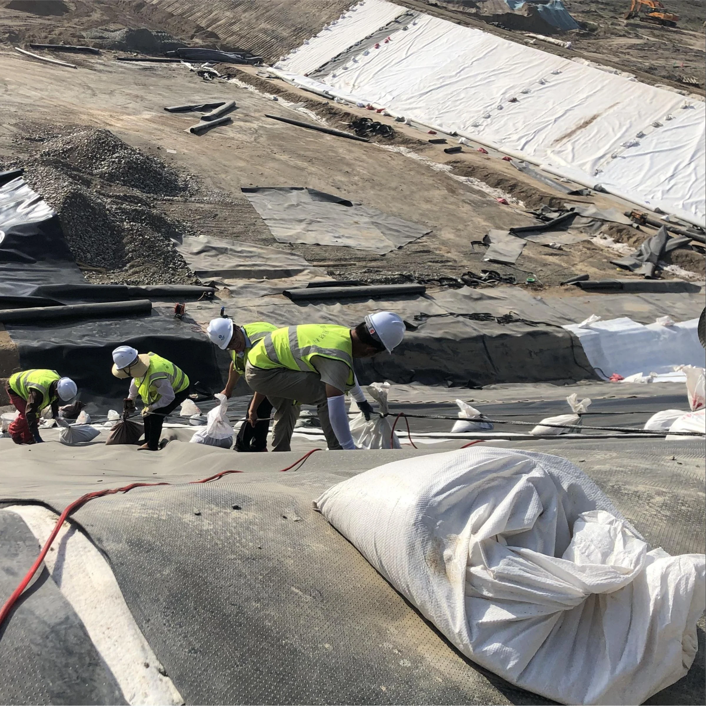
Bottom to top the single build-up runs foundation, cushion geotextile, primary membrane, then cover soil or ballast. Foundation compaction holds at 90 percent or better, and the liner itself has to stop waste migrating into adjacent soil or ground water. [5]
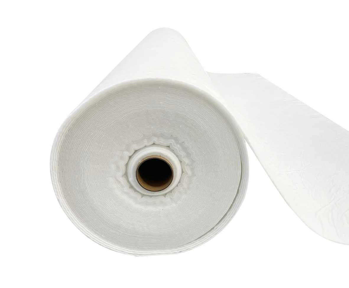
The cushion runs 300 to 500 g/m² of PET filament nonwoven geotextile, or a dedicated membrane protection geotextile. Grab tensile to D4632 and static puncture to D6241 govern that geotextile, with cushion installation and membrane puncture protection sitting underneath both. [5][15][16]
Double liner build-up
Industrial effluent, or a jurisdiction that demands secondary containment, drives the double build-up, running bottom to top through foundation, lower compacted soil, leak detection layer, upper geomembrane, cushion geotextile and cover soil, and the same stack sits under a landfill bottom liner. [5]
The leachate collection and removal system between the leak detection system and the top liner doubles as the leak detection system itself. It must provide a bottom slope of at least 1 percent, and either a granular drainage material with a hydraulic conductivity of at least 1×10⁻¹ cm/s and a thickness of at least 12 in, or 30.5 cm, or a synthetic or geonet drainage material with a transmissivity of at least 3×10⁻⁴ m²/s.
It must be built from materials chemically resistant to the waste and expected leachate, with enough strength and thickness to avoid collapsing under the waste and equipment above, and designed to resist clogging during the active life and after closure. [5]
40 CFR 264.222 caps the action leakage rate at the most the leak detection system can remove while head on the bottom liner stays under 1 ft, or 30.5 cm. Reporting runs in gallons per acre per day. [17]
Exceeding that ceiling triggers written notice to the regulator within 7 days, with a preliminary assessment in 14. [18]
Welding and testing
Rolls laid side by side share a seam, so each roll carries 140 m of weld, or 0.125 m per square metre, and seam area comes to 1.6 percent of the membrane.
A 37,000 m² job carries about 4,625 m of seam, and at 4 m per minute over 6 effective hours a dual-track wedge covers 1,440 m a shift, so field work takes about 3 shifts.
Overlap runs 100 to 150 mm, and overlap and wastage calculation covers how that width turns into material loss.
Seam air testing holds 0.25 MPa for 5 minutes with no pressure drop, or 2.5 bar and 36 psi, run as a dual-seam air channel to D5820, and every shift opens with 1 trial weld sent to peel testing with the pass line set by D6392. [19][20]
An electrical survey to ASTM D7007 leak location closes the job, and the sweep covers every seam and every penetration. Method selection follows D6747, and non-destructive seam checks beyond the destructive trial weld follow D4437. [21][22][23]
Anchoring, penetrations, venting
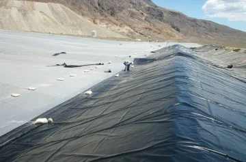
Lagoons holding wastewater or manure must vent under the membrane. Crest vents sit no more than 50 ft apart, or 15.2 m. [1]
A 30,000 m² floor measures 173 m a side. With 10.1 m of shoulder added on each side, the crest perimeter runs 773 m and carries 51 vents. [1]
Floors with an underliner drainage system slope at 1 percent or more, and those without bottom venting slope at 2 percent, because a missed vent leaves bulges and wrinkles across the sheet. [1]
An anchor trench 254 mm deep and 305 mm wide takes about 53.6 m³ of excavation and backfill around the 692 m perimeter. Trench dimensions and backfill requirements start at 203 to 305 mm.
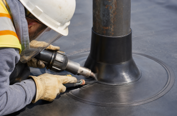
Inlet pipes, outlet pipes and aerator supports each count as a separate penetration, and every one gets a flange or heat-fused sleeve, its own patch weld and seal, plus 100 percent photographic records at handover.
Rules and paperwork
Jurisdiction floors
Two municipal solid waste landfill regimes make a clean comparison. 40 CFR 258.40(b) asks for a flexible membrane liner of at least 30 mil, HDPE at least 60 mil, over at least 2 ft or 60 cm of compacted soil at no more than 1 x 10⁻⁷ cm/s. [24]
GB 16889 asks for 0.75 m of clay over a 2 m natural foundation layer, and both regimes hold leachate head over the liner inside 30 cm. [24][25]
258.40(b) goes further, holding the lower compacted soil at 2 ft or 60 cm deep and the leachate collection at less than 30 cm of head over the liner, and GB 16889 caps leachate depth at the same 30 cm. [24][25]
At the regulatory ceiling of 1 x 10⁻⁷ cm/s on unit gradient, 91 cm of clay takes about 29 years to pass water through. Measured seepage runs the other way. The 0.76 cm/d in Table 3 works back to roughly 1.3 x 10⁻⁶ cm/s, thirteen times the ceiling.
EU directive 1999/31/EC sets its own numbers, in Annex I point 3.2, where hazardous waste landfills take K of no more than 1.0 x 10⁻⁹ m/s over at least 5 m and non-hazardous waste takes the same K over at least 1 m. [26]
Inert waste takes 1.0 x 10⁻⁷ m/s over at least 1 m, and an artificial barrier 0.5 m or more. Only the millimetre thickness of the artificial sealing layer is left to member states, while Chinese projects also clear GB/T 17643 on polyethylene geomembrane specification and factory testing. [26][27]
Acceptance file
Factory testing runs on tonnage bands, with thickness every roll, tensile and carbon black every 9,000 kg, tear, puncture and carbon black dispersion every 20,000 kg, and density and OIT every 90,000 kg. [3]
Density, carbon black and OIT lines carry the UV and oxidation resistance of the sheet, so each one gets checked line by line at handover.
An 11-roll order is 17.4 t, which brings 11 thickness records, 2 tensile reports, 2 carbon black reports, 1 tear and puncture report and 1 density and OIT report.
- Per-roll factory reports covering thickness, density, tensile, puncture and OIT
- Trial weld and peel records for every shift, with welder ID and machine settings
- Electrical leak survey map after cover placement, with all patch coordinates
Service life and upkeep
Design life for a buried 1.5 mm HDPE sheet runs 50 to 100 years on Arrhenius extrapolation, so read it as an industry range and nothing finer. [3]
Standard OIT floors at 100 minutes, high pressure OIT at 400 minutes, and a 90 day bake at 85 degrees Celsius, or 2,160 hours, leaves both above 55 and 80 percent. [28][29][3]
Exposed membrane is judged on UV resistance. GRI-GM13 asks high pressure OIT to hold 50 percent after 1,600 hours of fluorescent UV, or 67 days of continuous exposure, and evaporation and sludge lagoons running above 40 degrees Celsius follow those same two retention lines. [3][30]
Cleanout is the one time plant drives straight onto the sheet. Wheeled equipment needs a temporary protection sheet or a steel plate. Where there is visible current, cover soil goes above 25 cm, and that cover only works over erosion resistant cohesive soil. [4]
Patches overlap at 150 mm or more, one step tighter than the 100 to 150 mm used on field seams. Each patch takes its own air test, and repair methods and patch sizes follow the same floor.
Quantity and cost
Membrane quantity comes from three areas, the floor, the developed slopes and waste, where a 2-to-1 slope develops 2.24 m of slant per metre of rise and overlap only takes 1.3 to 2.6 percent.
Trimming and irregular edges take the rest, so the overall allowance runs 10 percent, or 15 percent on an irregular lagoon, and developed area and waste factors reproduce that figure.
A 30,000 m² floor plus 7,000 m² of slope gives 37,000 m², and adding 10 percent waste takes it to 40,700 m², or 36 rolls and about 57 t at 1.5 mm.
Fifty-seven tonnes fills 3 containers. A 40HQ holds 26 t, so the third one carries only 5 t.
At 5 to 8 USD per m² FOB factory, 40,700 m² costs USD 200,000 to USD 330,000. The range is an order of magnitude, and it excludes five items, ocean freight, welding, earthwork, anchor trenches and leak survey.
- Product type, high density or linear low density, smooth or textured
- Gauge or weight, for example 1.5 mm or 60 mil
- Roll format, 5.8 to 8.0 m wide by 70 to 210 m long
- Quantity in tonnes or square metres
- Destination port and port of loading
- Service, anaerobic, aerated, evaporation or secondary containment
Trial orders start at 1 to 3 t. Anything above 17 t is best packed into a full container. Standard grades ship in 7 to 15 days, and custom or peak season work runs 15 to 25 days.
Send the floor area, slope ratio, effluent pH and design life, and a 60 to 120 mil selection with roll quantities, a 40HQ loading plan and trial order pricing from 1 to 3 t comes back within 48 hours.Send parameters for a quote
Conversions and field tolerances
1 mil is 0.0254 mm, 1 kN/m is 5.71 lb/in, 1 N is 0.2248 lb, 1 g/m² is 0.0295 oz/yd², 1 lb/ft² is 4.88 kg/m², 1 kPa is 0.145 psi, and 1 cm/d is 10 L/(m²·d).
| Item | Given value | Converted or derived result |
|---|---|---|
| Puncture and tensile | 480 N, 40 kN/m | 108 lb, 228 lb/in |
| GCL dosage | 0.75 lb/ft² | 3.66 kg/m² |
| Cushion weight | 300 g/m² | 8.9 oz/yd² |
| Cushion quantity | 37,000 m² at 300 g/m² | 11.1 t, 6,200 m at 6 m width, about 44 rolls |
| GCL bentonite | 37,000 m² at 3.66 kg/m² | 135 t |
| Leak detection granular fill | 37,000 m² at 30.5 cm | 11,285 m³ |
| Lower compacted clay | 37,000 m² at 91 cm | 33,670 m³ |
| Cover layer | 37,000 m² at 25 cm | 9,250 m³ |
Industry conventions with no citation attached, applied by normal practice, and the 50 to 100 year service life of a buried 1.5 mm sheet sits in the same group. Foundation compaction at 90 percent or better, dual-track hot wedge welding, a seam air test at 0.25 MPa held for 5 minutes, a welding window of 200 to 350 degrees Celsius, cover soil above 25 cm, floor gravel held at 20 mm, cleanout plant ground pressure of 50 kPa, a wedge speed of 4 m per minute, and patch overlap at no less than 150 mm.
Sources
- U.S. Department of Agriculture, Natural Resources Conservation Service. Conservation Practice Standard 521, Pond Sealing or Lining, Geomembrane or Geosynthetic Clay Liner (Table 1 minimum thickness: HDPE 60 mil for wastewater and 30 mil for clear water, LLDPE 60 mil and 30 mil, GCL 0.75 lb per square foot of bentonite; gas vents at the crest spaced no more than 50 feet; minimum bottom grade of 2 percent where no bottom gas venting system is installed, at least 1 percent where an underliner drainage system is used). efotg.sc.egov.usda.gov
- Geosynthetic Institute. GRI Test Method GM17: Standard Specification for Test Methods, Test Properties and Testing Frequency for Linear Low Density Polyethylene (LLDPE) Smooth and Textured Geomembranes. geosynthetic-institute.org
- Geosynthetic Institute. GRI Test Method GM13: Standard Specification for Test Methods, Test Properties and Testing Frequency for High Density Polyethylene (HDPE) Smooth and Textured Geomembranes. geosynthetic-institute.org
- U.S. Environmental Protection Agency. Principles of Design and Operations of Wastewater Treatment Pond Systems for Plant Operators, Engineers, and Managers (EPA/600/R-11/088). Anaerobic ponds 2.5 to 4.5 m deep with 5 to 50 day detention, facultative ponds 0.9 to 2.4 m, mechanically aerated ponds 2 to 6 m, aerobic ponds 30 to 45 cm; measured seepage rates of 12 liner types at 6 m of water depth after 1 year of service (compacted earth 91 cm 0.76 cm/d, exposed synthetic membrane 0.11 cm 0.003 cm/d, open sand and gravel 244 cm/d); cover depth greater than 25 cm where significant hydraulic current is present. www.epa.gov
- U.S. Electronic Code of Federal Regulations. Title 40, Section 264.221: Design and operating requirements for surface impoundments (double liner with a leak detection and removal system between the liners, bottom slope of at least 1 percent, at least 3 feet or 91 cm of compacted soil with hydraulic conductivity no more than 1 x 10⁻⁷ cm/sec, granular drainage material with hydraulic conductivity of at least 1 x 10⁻¹ cm/sec and thickness of at least 12 inches or 30.5 cm, or geonet drainage with transmissivity of at least 3 x 10⁻⁴ m2/sec). www.ecfr.gov
- ASTM International. ASTM D5397: Standard Test Method for Evaluation of Stress Crack Resistance of Polyolefin Geomembranes Using Notched Constant Tensile Load Test. www.astm.org
- Geosynthetic Institute. GRI Guide GM10: Standard Guide for the Stress Crack Resistance of HDPE Geomembrane Sheet (NCTL transition time minimum 250 hours; SP-NCTL pass criteria 4 of 5 specimens with failure time above 500 hours and the remaining specimen above 250 hours). geosynthetic-institute.org
- ASTM International. ASTM D5887/D5887M: Standard Test Method for Measurement of Index Flux Through Saturated Geosynthetic Clay Liner Specimens Using a Flexible Wall Permeameter. www.astm.org
- ASTM International. ASTM D5514/D5514M: Standard Test Methods for Large-Scale Hydrostatic Puncture Testing of Geosynthetics. www.astm.org
- ASTM International. ASTM D5199: Standard Test Methods for Measuring the Nominal Thickness of Geosynthetics. www.astm.org
- ASTM International. ASTM D4833/D4833M: Standard Test Method for Index Puncture Resistance of Geomembranes and Related Products. www.astm.org
- ASTM International. ASTM D1004: Standard Test Method for Tear Resistance (Graves Tear) of Plastic Film and Sheeting. www.astm.org
- ASTM International. ASTM D5321/D5321M: Standard Test Method for Determining the Shear Strength of Soil-Geosynthetic and Geosynthetic-Geosynthetic Interfaces by Direct Shear. www.astm.org
- ASTM International. ASTM D7466: Standard Test Method for Measuring the Asperity Height of Textured Geomembrane. www.astm.org
- ASTM International. ASTM D4632/D4632M: Standard Test Method for Grab Breaking Load and Elongation of Geotextiles. www.astm.org
- ASTM International. ASTM D6241: Standard Test Method for Measuring Static Puncture Strength of Geotextiles and Geotextile-Related Products Using a 50-mm Probe. www.astm.org
- U.S. Electronic Code of Federal Regulations. Title 40, Section 264.222: Action leakage rate for surface impoundment units (maximum design flow rate the leak detection system can remove without the fluid head on the bottom liner exceeding 1 foot, reported as gallons per acre per day). www.ecfr.gov
- U.S. Electronic Code of Federal Regulations. Title 40, Section 264.223: Response actions when the action leakage rate is exceeded (written notice within 7 days, preliminary written assessment within 14 days). www.ecfr.gov
- ASTM International. ASTM D5820: Standard Practice for Pressurized Air Channel Evaluation of Dual-Seamed Geomembranes. www.astm.org
- ASTM International. ASTM D6392: Standard Test Method for Determining the Integrity of Nonreinforced Geomembrane Seams Produced Using Thermo-Fusion Methods. www.astm.org
- ASTM International. ASTM D7007: Standard Practices for Electrical Methods for Locating Leaks in Geomembranes Covered with Water or Earth Materials. www.astm.org
- ASTM International. ASTM D6747: Standard Guide for Selection of Techniques for Electrical Leak Location of Leaks in Geomembranes. www.astm.org
- ASTM International. ASTM D4437/D4437M: Standard Practice for Nondestructive Testing (NDT) for Determining the Integrity of Seams Used in Joining Flexible Polymeric Sheet Geomembranes. www.astm.org
- U.S. Electronic Code of Federal Regulations. Title 40, Section 258.40: Design criteria for municipal solid waste landfill units. www.ecfr.gov
- Ministry of Ecology and Environment of the People’s Republic of China. GB 16889-2008 Standard for pollution control on the landfill site of municipal solid waste (clay layer below the liner at least 0.75 m, natural foundation layer at least 2 m, permeability below 1.0 x 10⁻⁷ cm/s, leachate depth above the liner no more than 30 cm) [in Chinese]. www.mee.gov.cn
- European Commission. Landfill waste. ec.europa.eu
- State Administration for Market Regulation of China. National standards full-text public system, GB/T 17643 polyethylene geomembrane [in Chinese]. openstd.samr.gov.cn
- ASTM International. ASTM D5885/D5885M: Standard Test Method for Oxidative Induction Time of Polyolefin Geosynthetics by High-Pressure Differential Scanning Calorimetry. www.astm.org
- ASTM International. ASTM D3895: Standard Test Method for Oxidative-Induction Time of Polyolefins by Differential Scanning Calorimetry. www.astm.org
- ASTM International. ASTM D7238: Standard Test Method for Effect of Exposure of Unreinforced Polyolefin Geomembrane Using Fluorescent UV Condensation Apparatus. www.astm.org