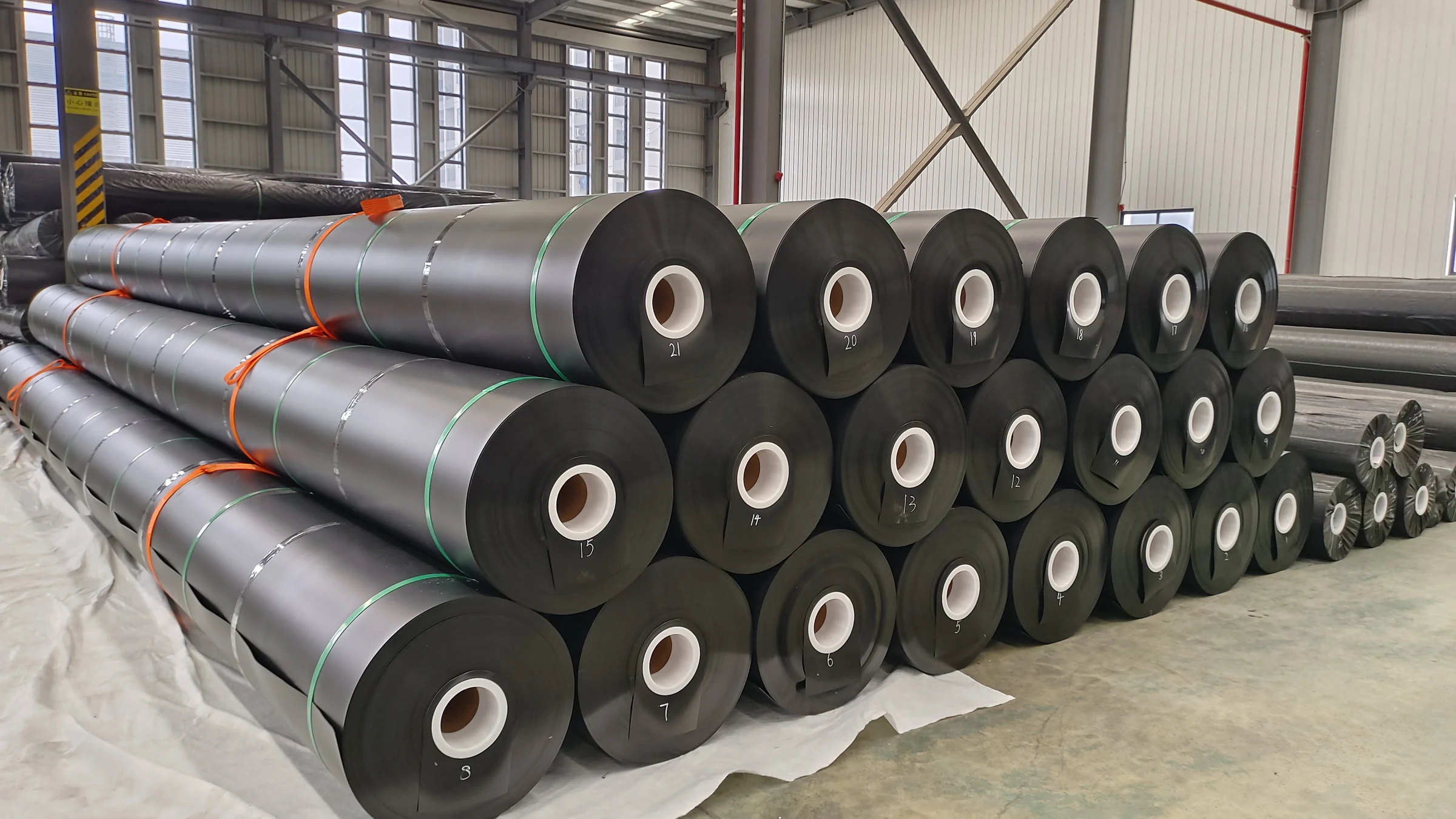
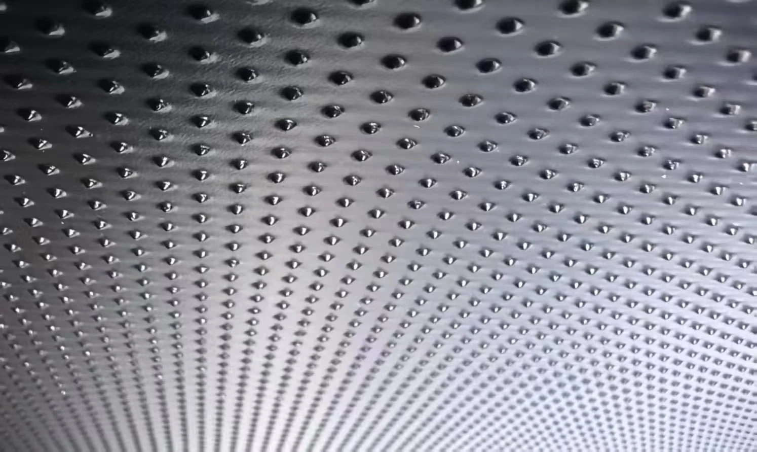
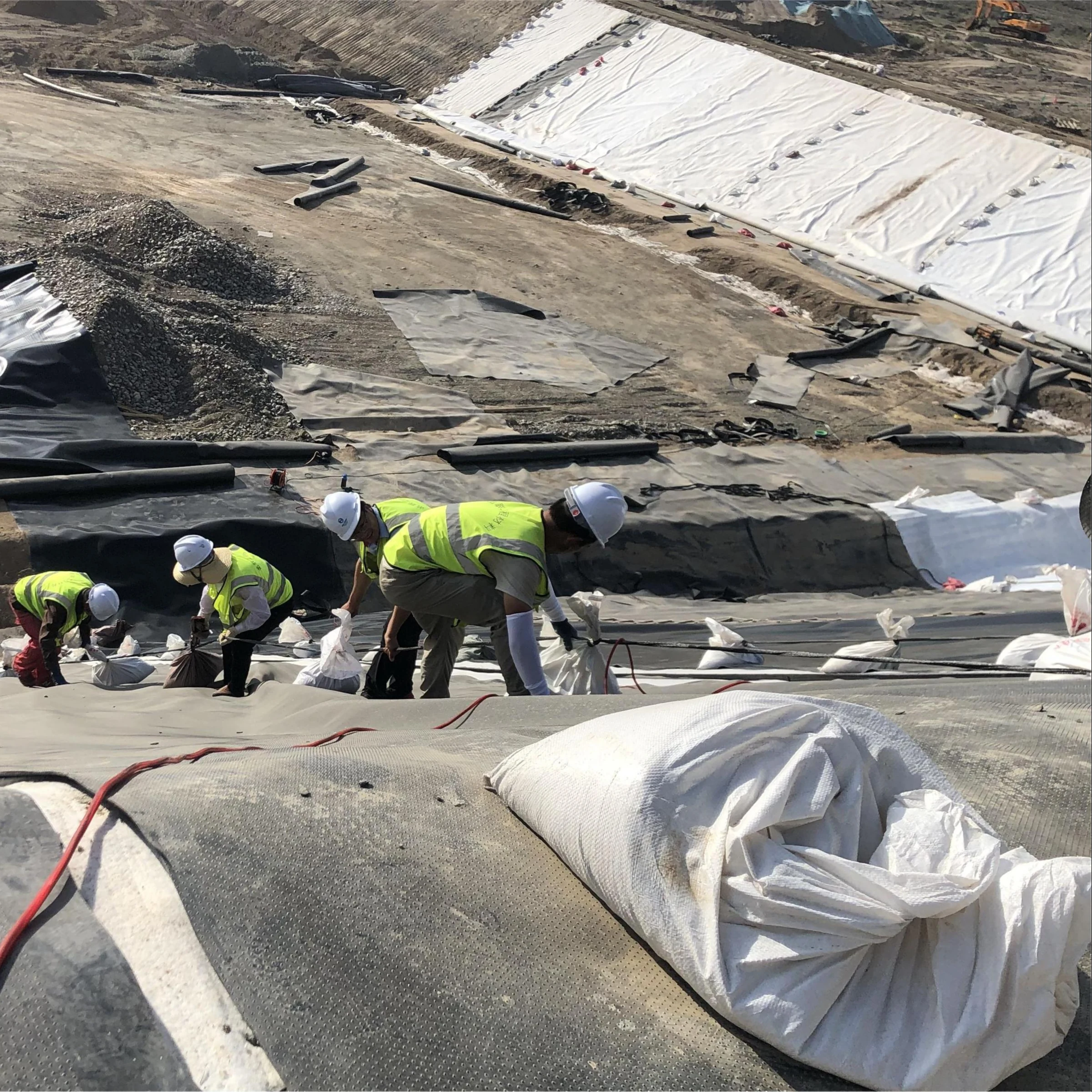

When a crack, split, or tear is discovered in an installed geomembrane liner, identifying the underlying failure mechanism is critical before executing permanent repairs. In containment applications—particularly those using high-density polyethylene (HDPE) geomembranes—investigators must distinguish between environmental stress cracking (slow crack growth) and direct mechanical damage. While mechanical damage stems from external physical forces such as puncture, impact, abrasion, or tearing during handling and construction, stress cracking is a time-dependent brittle fracture mechanism driven by sustained tensile stress below the polymer’s short-term yield strength. Because surface appearance alone cannot reliably establish the root cause—and because a mechanical surface scratch often acts as the stress-concentrating notch that initiates slow crack growth—a valid root cause investigation must combine field defect mapping, fracture morphology examination, Construction Quality Assurance (CQA) installation records, and targeted laboratory testing.
Patching a visible opening without investigating why it formed leaves the containment system vulnerable to recurring failures. If a liner splits due to unaddressed bridging stress or subgrade settlement, a welded repair patch over the same restrained zone may simply transfer tensile strain to the perimeter of the new weld. Conversely, assuming a linear slit is a material stress crack when it was actually caused by construction equipment traffic can trigger unnecessary material disputes while the real site hazard remains unmanaged.
1. What Is Geomembrane Stress Cracking?
Geomembrane stress cracking—formally categorized in polymer engineering as Slow Crack Growth (SCG) or Environmental Stress Cracking (ESC)—is a quasi-brittle failure mechanism that occurs when a semi-crystalline polyolefin liner remains under sustained tensile load over an extended period. Crucially, stress cracking develops at stress levels significantly lower than the material’s short-term tensile yield strength or break strength measured during standard quality control tensile tests.
At the microstructural level, HDPE consists of crystalline lamellae connected by amorphous regions containing “tie molecules.” Under prolonged localized tension, these tie molecules gradually disentangle and pull out of the crystalline blocks rather than stretching with visible ductile yielding. Elevated temperatures, chemical exposure, or wetting agents can accelerate this disentanglement process.
Stress cracking is an important engineering concern for HDPE geomembranes. Resistance depends on resin structure, additives, processing, exposure and stress concentration. More flexible polymers behave differently, but lower density alone does not prove immunity from damage or establish service life.
2. What Is Mechanical Damage?
Mechanical damage refers to any physical breach, deformation, or surface degradation caused by direct external force applied to the geomembrane during manufacturing, transportation, unloading, deployment, seaming, or cover placement. Unlike slow crack growth, mechanical damage typically occurs during a discrete physical event when an applied load exceeds the local puncture, tear, impact, or abrasion resistance of the sheet.
Depending on the geometry of the contacting object and the speed of impact, mechanical damage may manifest as:
- Punctures and perforations from angular subgrade stones, tools, or dropped hardware.
- Gouges, scratches, and scoring caused by dragging panels over rough surfaces or excessive grinding during extrusion weld preparation.
- Tears and tensile splits triggered by improper lifting equipment, wind uplift during deployment, or machinery braking and turning on unprotected liner panels.
- Crushing or localized thinning beneath heavy construction traffic or poorly graded drainage aggregate.
3. Key Differences Between Stress Cracking and Mechanical Damage
While definitive classification requires a complete forensic review, stress cracking and mechanical damage differ across their physical mechanisms, fracture characteristics, spatial patterns, and progression timelines.
| Investigation Parameter | Geomembrane Stress Cracking (Slow Crack Growth) | Mechanical Damage |
|---|---|---|
| Primary Mechanism | Sustained tensile stress below short-term yield strength leading to progressive slow crack growth. | Direct external physical force exceeding local puncture, tear, shear, or tensile limits. |
| Typical Fracture Morphology | Quasi-brittle, relatively flat fracture plane perpendicular to the stress direction; minimal or no visible necking (thinning) at crack edges. | Often exhibits ductile deformation, localized stretching, thinning (necking), ragged edges, gouge tracks, or indentation marks. |
| Common Locations | Areas of high restraint and geometric transition: adjacent to extrusion/fusion welds (HAZ), anchor trench corners, pipe penetrations, and bridged wrinkles. | Exposed work zones, equipment haul paths, panel edges, unloading areas, and over poorly prepared subgrade protrusions. |
| Time Dependency | Time-dependent; initiates at a microscopic defect or notch and propagates over weeks, months, or years. | Often linked to handling, installation or covering events; abrasion and repeated loading may also accumulate over time. |
| Primary Investigation Focus | Thermal contraction restraint, subgrade settlement, weld geometry, surface notches, and resin stress crack resistance. | CQA deployment logs, equipment traffic control, subgrade acceptance records, and protective layer placement methods. |
| Corrective Priority | Relieve tensile restraint, eliminate geometric stress concentrators, and verify material suitability for service conditions. | Remove physical hazards, upgrade subgrade/cushion protection, enforce site traffic rules, and repair damaged panels. |
Engineering Caution: The traits listed above serve as investigative indicators, not standalone visual acceptance criteria. For example, a high-speed mechanical impact at freezing temperatures can produce a sharp, brittle-looking split in polyethylene, whereas a stress crack initiated by a deep mechanical gouge will display both abrasion marks and brittle propagation features.
4. Common Causes of HDPE Geomembrane Stress Cracking
Even when an HDPE geomembrane is manufactured from high-performance resin, slow crack growth can develop if field conditions combine sustained tensile strain with localized stress concentration.
4.1 Localized Tensile Stress and Restraint
Polyethylene has a relatively high coefficient of thermal expansion and contraction. If a liner is deployed and welded during high daytime temperatures without sufficient slack (compensation), overnight or seasonal cooling induces significant contraction stress. Concentration points frequently develop around:
- Weld Heat-Affected Zones (HAZ): Extrusion fillet welds and dual-track hot wedge seams create abrupt changes in sheet thickness and thermal history right at the edge of the weld bead.
- Structural Transitions: Pipe boots, concrete batten strips, sump corners, and steep slope-to-floor transitions where the liner cannot move freely.
4.2 Wrinkles, Bridging, and “Trampolining”
When panels are welded with excessive thermal wrinkles that are subsequently flattened or bridged under heavy overburden—or when a liner spans across a void at the toe of a slope (“trampolining”)—the unsupported sheet is forced into sustained bending and tensile strain. Over time, folded wrinkle peaks and bridged transitions become prime locations for slow crack growth.
4.3 Differential Subgrade Settlement
Uneven consolidation beneath landfill cells, heap leach pads, or wastewater lagoons imposes long-term multiaxial strain on the liner system. Differential settlement around rigid structures (such as concrete manholes or leachate collection sumps) creates high shear and tensile loads right at the connection interface.
4.4 Resin Formulation, Processing, and Oxidative Degradation
A geomembrane’s intrinsic resistance to slow crack growth depends on polymer molecular weight distribution, comonomer type and distribution, carbon black dispersion, and processing thermal history. Furthermore, if the antioxidant package is depleted over time due to prolonged UV exposure, elevated temperatures, or aggressive chemical leachate, surface oxidation can embrittle the polymer skin and drastically reduce stress crack resistance.
5. Common Sources of Mechanical Damage During Installation
Mechanical defects can be introduced at any stage from factory load-out to final cover placement. Common field sources include:
- Improper Unloading and Roll Handling: Using unapproved steel cables, chains, or forklift tines without spreader bars or core stingers, which can crush roll edges or gouge outer wraps.
- Subgrade Protrusions: Deploying panels over uncompacted subgrades containing angular stones, fractured rock, tree roots, or construction debris.
- Deployment Dragging and Abrasion: Dragging panels across rough soil or existing textured geosynthetics rather than floating or rolling them into position.
- Weld Preparation Grinding: Over-grinding the sheet surface prior to extrusion welding. Deep grinding scratches oriented parallel to the seam edge reduce local sheet thickness and create severe mechanical notches.
- Unprotected Equipment Traffic: Allowing skid-steers, dump trucks, or excavators to drive directly on the bare geomembrane or make sharp pivot turns over thin protective cover layers.
- Cover Material Placement: Dumping drainage gravel or protective soil from excessive drop heights, or pushing aggregate upslope vs. downslope with dozer blades too close to the liner.
How Mechanical Damage Triggers Stress Cracking (The Compound Mechanism)
In field investigations, stress cracking and mechanical damage frequently overlap. A shallow mechanical scratch, stone indentation, or excessive grinding score can leave a surface notch without creating a leak path through the liner. Conductive-backed spark testing locates breaches under suitable test conditions, and vacuum-box testing checks for leaks at suitable seams, patches or defects. Neither method measures the depth of a non-penetrating scratch. Document such marks during visual inspection and assess them against the project criteria. The notch can act as a geometric stress concentrator under sustained loading from thermal restraint or overburden and may contribute to slow crack growth.
6. How to Investigate the Root Cause of Geomembrane Cracking
A credible failure analysis follows a structured engineering workflow that moves from non-destructive field documentation to historical record reconstruction and, where needed, laboratory forensics.
Step 1: Preserve the Scene and Map Crack Distribution
Never cut out or patch a disputed crack before documenting it in place. Once a repair patch is welded over the defect, critical evidence regarding sheet tension, bridging, and subgrade contact is permanently destroyed.
- Measure the width of the gap between the separated crack edges. When a crack opens wide immediately upon splitting, it indicates the panel was under active tensile strain (bridging or thermal contraction).
- Map the exact coordinates of every defect on the as-built panel layout drawing to identify spatial patterns—such as cracks repeating along a specific haul road, aligning along the south-facing slope (high UV/thermal cycling), or clustering within a single roll batch.
Step 2: Examine Fracture Characteristics and the Surrounding Subgrade
Before sampling, inspect both the top and bottom surfaces of the liner and the underlying layers:
- Check whether the crack initiates from the top surface (often associated with grinding scores, equipment gouges, UV oxidation, or surface bending tension) or the bottom surface (often linked to angular subgrade stones or upward protrusion point loads).
- Carefully expose the subgrade or geosynthetic clay liner (GCL) directly beneath the crack to look for protruding stones, ruts, voids, or differential settlement steps.
Step 3: Reconstruct the CQA and Installation Timeline
Cross-reference the defect location against project quality documentation to determine when and how the area was handled:
| Project Record | Key Investigation Questions |
|---|---|
| Roll & Batch Certificates | Do the cracked panels belong to a single manufacturing lot or multiple batches? |
| Delivery & Unloading Logs | Were roll damage notes recorded upon arrival? What lifting gear was used? |
| Subgrade Acceptance Forms | Was the area inspected and signed off immediately prior to panel deployment? |
| Panel Placement Logs | What was the ambient temperature during deployment? Was sufficient thermal slack provided? |
| Seaming & Trial Weld Logs | Did the crack occur next to a reworked extrusion patch, repair weld, or over-heated seam? |
| NDT & Leak Location Reports | Did the area pass air pressure, vacuum box, or electrical leak location (ELL) testing prior to covering? |
| Cover Placement Records | What equipment placed the protective geotextile and drainage stone, and along which access routes? |
Step 4: Select Appropriate Laboratory Testing
When field evidence is inconclusive or when multiple parties dispute responsibility, remove representative samples (including both the intact fracture faces and adjacent uncracked material) for independent laboratory examination.
7. What Field Evidence Should Be Collected?
To support an objective engineering evaluation, field teams should collect a standardized evidence package before authorizing repairs:
- High-Resolution Macro Photography: Photograph the overall panel context, the specific defect with a calibrated ruler for scale, and close-up oblique angles showing surface scratches, grinding marks, or deformation around the fracture edges.
- Defect Orientation and Geometry Notes: Record whether the crack runs parallel to the roll machine direction (MD), cross-machine direction (XMD), or strictly parallel to an extrusion/fusion weld bead.
- In-Situ Tension Observations: Document whether the liner is drum-tight (bridging over a toe or trench) or resting flush against the subgrade, and measure the opening width of the split.
- Physical Cutout Samples: Cut a sample generously around the crack (when approved by the project engineer) without touching, pressing, or contaminating the opposed fracture surfaces. Protect the fracture faces with clean padding during shipping so microscopic surface features are not rubbed away.
- Subgrade and Interface Samples: Photograph and, if relevant, collect the specific stone, debris, or underlying geotextile directly beneath the failure point.
8. When Is Laboratory Testing Necessary—and What Does ASTM D5397 Actually Show?
Laboratory testing is essential when field inspection cannot separate installation damage from material performance issues, or when project stakeholders must verify whether the remaining installed liner is at risk of systemic slow crack growth.
A comprehensive forensic laboratory program typically involves:
- Optical and Scanning Electron Microscopy (SEM) Fractography: Examining the fracture face to identify the exact point of crack initiation (top vs. bottom surface, mechanical notch vs. internal inclusion) and the mode of propagation (brittle fibril structure typical of slow crack growth vs. ductile shear tearing).
- Cross-Sectional Microtomy: Slicing across the weld or crack profile to measure residual sheet thickness, grinding depth, and weld geometry stress concentrators.
- Oxidative Induction Time (OIT — ASTM D3895 / D5885): Assessing whether the antioxidant package remains intact or has been depleted by environmental exposure.
- Stress Crack Resistance Testing (ASTM D5397): Evaluating the intrinsic slow crack growth resistance of the uncracked sheet.
Understanding the Role and Limits of ASTM D5397
ASTM D5397 is an accelerated notched constant-load index test for susceptible polyolefin geomembranes. In the GRI-GM13 single-point approach, testing is commonly specified at 30% of yield stress and 50°C; use the exact contract edition and laboratory procedure for specimen preparation, test solution, loading and acceptance. These conditions are not field service ratings.
Engineers must interpret ASTM D5397 within its proper technical boundaries:
- It Is an Index and Qualification Test, Not a Standalone Root Cause Determiner: Passing or failing ASTM D5397 demonstrates the base sheet’s relative resistance to slow crack growth under accelerated laboratory conditions. It does not prove by itself why a specific field crack occurred—because even a liner with high SP-NCTL performance can crack in the field if subjected to severe mechanical notching, excessive weld overheating, or extreme bridging strain.
- Material Applicability Limits (HDPE vs. LLDPE): ASTM D5397 cannot be applied to polyolefin geomembranes without a clearly defined yield point. Some LLDPE and VLDPE formulations fall into this group. Confirm that the specific sheet has a defined yield point and otherwise meets the method’s scope before specifying the test. Use the applicable material specification and project acceptance criteria.
9. What Corrective Actions Should Be Considered?
Effective corrective action must address both the physical opening in the liner and the mechanism that caused it:
- When Mechanical Damage Is Confirmed:
- Remove the offending physical hazard (screen or re-roll the subgrade, revise the protective geotextile system based on the project puncture protection design, including the actual aggregate, liner and loading conditions, or modify aggregate placement drop heights).
- Repair small punctures or localized tears using approved extrusion patches or cap strips in accordance with project CQA specifications.
- Replace entire panel sections if heavy equipment traffic has caused widespread scraping, deep rutting, or severe sheet thinning.
- When Stress Cracking or High Restraint Is Identified:
- Do not simply weld a flat patch over a bridged or drum-tight liner. First relieve the tensile restraint—for example, by cutting out the bridged transition and installing a wide cap strip or slack panel (“boot” or bellows detail) that sits fully supported against the subgrade.
- Inspect all similar geometric locations across the site (such as adjacent sump corners, pipe penetrations, or rework welds from the same shift) to catch incipient surface cracks before cover placement.
- If laboratory testing reveals systemic material degradation or non-conformance within a specific production batch, work with the project engineer to evaluate the affected lot’s service environment and determine whether targeted replacement or operational modifications are required.
10. How Can Similar Damage Be Prevented?
Preventing liner failures requires coordinated controls across material procurement, design detailing, and field installation:
- Specify Application-Appropriate Resin and Standards: For exposed or chemically demanding HDPE applications, verify that material specifications align with recognized industry benchmarks such as GRI-GM13, including verified SP-NCTL stress crack resistance and OIT retention. Select LLDPE where high multiaxial elongation or differential settlement tolerance is prioritized over HDPE stiffness.
- Review Batch QC Documentation Before Deployment: Audit resin lot numbers, roll manufacturing certificates, and third-party conformance test reports prior to panel layout.
- Eliminate Geometric Stress Concentrators in Design: Detail smooth transitions at anchor trenches, sumps, and concrete structures, and select cushion geotextiles beneath coarse drainage stone using the project’s puncture protection design and applicable performance evidence. Mass per unit area alone does not establish protection.
- Control Thermal Slack and Wrinkle Management: Schedule final tie-in welds at temperatures that prevent severe overnight bridging, and eliminate folded wrinkles before placing overburden.
- Enforce Strict Grinding and Extrusion Welding Discipline: Train technicians not to grind beyond the area covered by the extrusion bead, and prohibit deep gouging parallel to seam edges.
- Maintain Rigorous Subgrade and Traffic Controls: Before allowing machinery over the liner, verify that the cover thickness and placement sequence meet the project design and approved construction method, including the ground contact pressure limits for the actual equipment. Conduct post-cover Electrical Leak Location (ELL) surveys where specified.
Frequently Asked Questions (FAQ)
Can mechanical damage and stress cracking occur at the same defect location?
Yes, and this is one of the most common findings in field failure investigations. An installation scratch, stone indentation, or deep grinding mark next to an extrusion weld acts as a sharp geometric notch. When the liner subsequently experiences thermal contraction or overburden tension, stress concentrates at the bottom of that mechanical notch and initiates slow crack growth through the remaining thickness.
Why do cracks frequently appear right next to geomembrane extrusion welds?
The edge of an extrusion weld combines three vulnerability factors: a sharp geometric step where the thick weld bead meets the base sheet, mechanical grinding scratches from surface preparation, and thermal alteration in the Heat-Affected Zone (HAZ). If the panel is pulled under tension perpendicular to the seam, stress concentrates along the toe of the weld bead.
Does a passing ASTM D5397 (SP-NCTL) result guarantee that an HDPE liner will never stress crack in the field?
No. ASTM D5397 is an accelerated laboratory index test that confirms the resin and sheet formulation meet baseline slow crack growth resistance under standardized conditions. However, severe field installation defects—such as deep grinding gouges, bridged voids at slope toes, or uncompensated thermal restraint—can induce localized strains and notch effects that exceed safe design limits.
Can you tell the difference between stress cracking and mechanical tearing by eye alone?
Visual inspection provides useful initial clues—such as flat, brittle-looking edges in stress cracks versus stretched, thinned, or scratched edges in mechanical tears—but visual appearance alone is not conclusive. Cold-temperature impact can cause brittle fractures from purely mechanical forces, and weathered mechanical cuts can mimic stress cracks. Definitive root cause confirmation requires reviewing CQA history and, in disputed cases, microscopic examination of the fracture surface.
Conclusion
Distinguishing geomembrane stress cracking from mechanical damage requires looking beyond the visible opening in the sheet. By systematically preserving field evidence, analyzing fracture morphology, auditing CQA deployment and welding logs, and applying laboratory methods like microscopy and ASTM D5397 within their proper technical scope, project teams can identify the true failure mechanism and implement lasting engineering solutions.
Whether your project calls for high stress-crack-resistant HDPE geomembranes for landfill and mining containment or high-elongation LLDPE geomembranes for substrates prone to differential settlement, selecting the right material specification and installation protocol is the foundation of long-term liner integrity. To review technical datasheets, batch quality control procedures, or project-specific liner options, explore Jinseed’s geomembrane product specifications or connect with Jinseed to discuss the specified material and documentation requirements. Failure diagnosis and repair approval remain with the project engineer and qualified investigation team.
Technical References and Related Resources
- ASTM D5397 — stress-cracking index test and material applicability
- Geomembrane material approval and roll traceability
Use the edition and acceptance criteria identified by the project contract. Material test compliance does not replace design approval or site acceptance. Send Jinseed your specification and project requirements.