


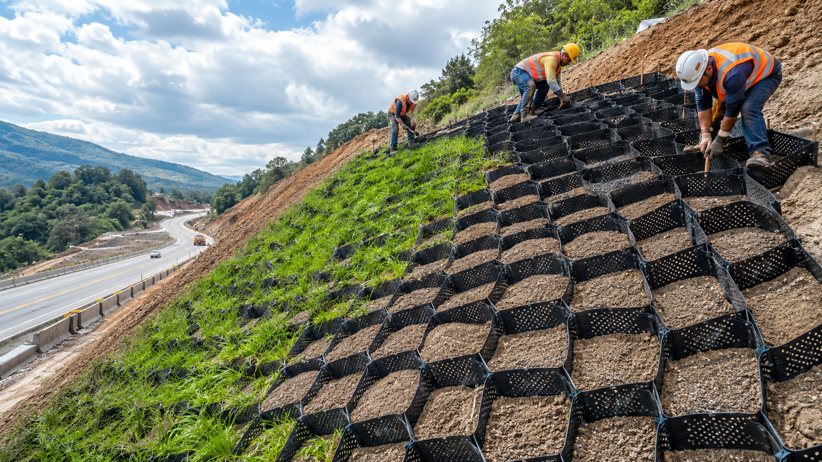
Installing geocells for slope erosion control requires a prepared slope, a verified anchoring system, suitable infill and an establishment plan for vegetation. The cells confine the surface material; they do not automatically stabilize a deep landslide or replace drainage design. Confirm the slope’s geotechnical condition and the approved construction details before deployment.
This guide provides a field planning sequence. Numerical examples are illustrative calculations, not documented Jinseed installation results. Anchor spacing, cell depth, infill grading and cover requirements must come from the selected system’s approved design.
1. Establish the slope geometry and drainage conditions
Survey slope height, face length, width, transitions, crest and toe. Write the slope convention explicitly. A 2H:1V slope has an angle of approximately 26.6°, while 1.5H:1V is approximately 33.7°. These are not the same as 2° or 1.5°, and neither ratio establishes that a particular geocell product is suitable.
Identify water arriving from the uphill catchment, sheet runoff on the face, groundwater seepage, outlets and toe scour. A crest diversion may be required to prevent concentrated flow entering a vegetated slope, but its alignment and discharge point need a hydraulic design. Do not discharge a collector onto an unprotected toe or adjacent property.
| Input | Field information to provide | Decision it supports |
|---|---|---|
| Slope and soil | Survey, soil description, soft zones, erosion and settlement evidence | Suitability of surface protection and foundation preparation |
| Water | Catchment, design event, seepage and outlet conditions | Drainage, infill type and erosion resistance |
| Infill | Grading, unit weight, placement method and vegetation suitability | Cell dimensions, anchor demand and placement procedure |
| Interfaces | Geotextile, geomembrane or soil beneath the cells | Sliding resistance and permissible anchorage details |
| Access | Equipment positions, lifting and working-space constraints | Deployment and controlled filling sequence |
2. Select the geocell and infill as a system
GRI-GS15 Revision 2, June 9, 2026, addresses manufacturing properties and testing for geocells made from HDPE strips. It is not a project-specific anchor layout or a guarantee that any material meeting it will suit every slope. Request the named product’s strip, seam, durability and dimensional documentation, together with the required connections and anchoring accessories.
Select cell depth and opening size with the intended infill, loading and installation method. Increasing depth adds infill weight as well as confinement. It cannot be treated as an unconditional improvement where anchor capacity or a weak underlying interface governs.
| Infill option | Suitable design objective | Important checks |
|---|---|---|
| Planting soil | Vegetated surface protection | Rooting, fertility, moisture, erosion before establishment and approved seed mix |
| Aggregate | Nonvegetated erosion protection | Grading, durability, particle size relative to the cells, hydraulic exposure and toe support |
| Engineered soil–aggregate blend | Balance between vegetation and granular support | Blend specification, uniformity, compaction and plant establishment |
| Concrete | Hard-armored protection where specified | Structural and hydraulic details, placement, drainage and system compatibility |
Do not prescribe well-graded fill for every function. A planting medium, a free-draining aggregate and a compacted structural fill have different grading needs. Particles must fit the deployed cells and approved filling method without bridging or damaging the walls and junctions. A visual field screen cannot replace required aggregate testing.
Presto’s GEOWEB technical overview distinguishes vegetated, aggregate and concrete infill and explains that runoff exposure, interfaces and anchorage affect selection. Its details are system-specific. Do not transfer its product dimensions, flow limits or accessory capacities to another manufacturer’s cells without substantiation.
3. Prepare the slope and install any filter or drainage layer
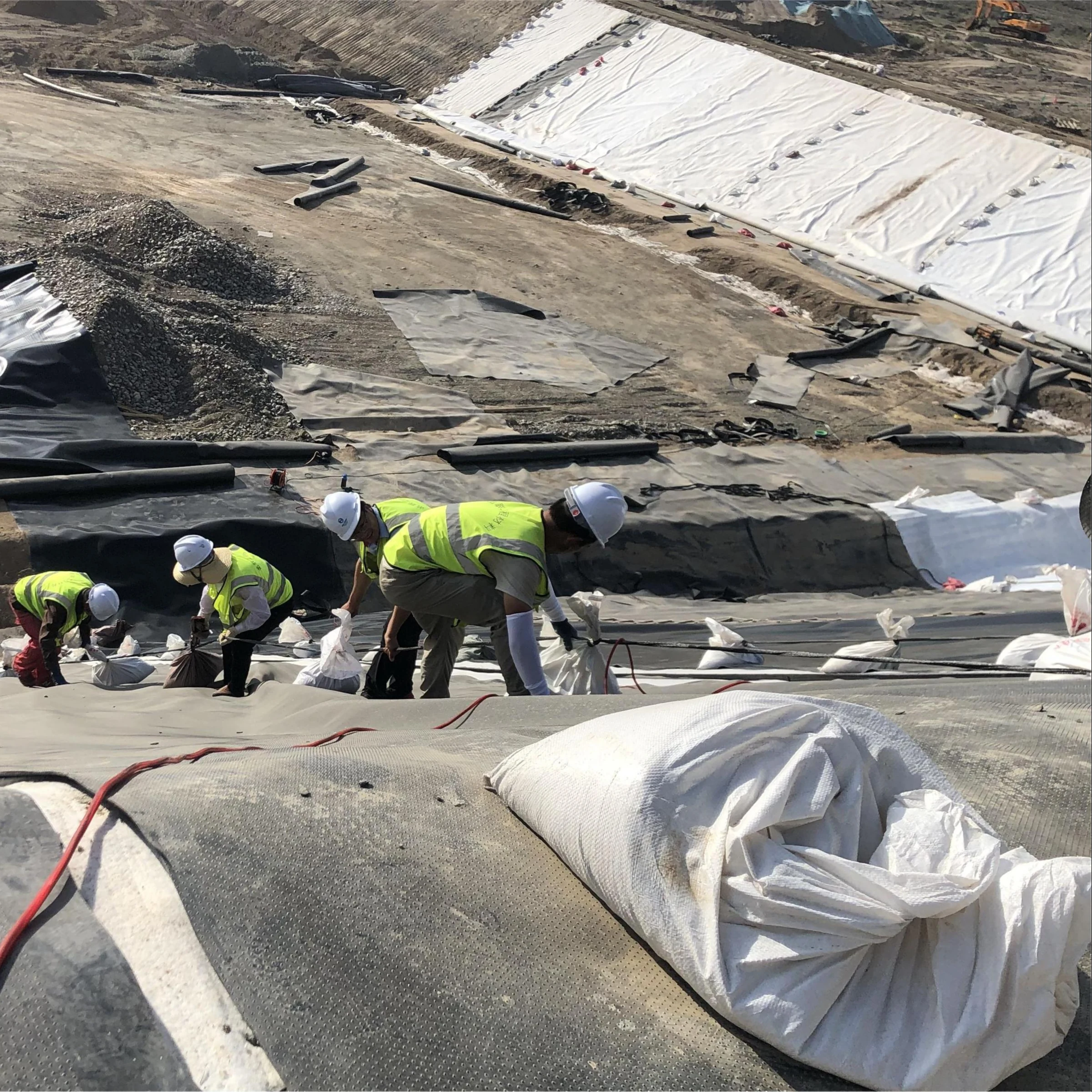
Complete approved grading and remove damaging protrusions, roots or loose material. Resolve soft spots and unexpected seepage before concealing them. The deployed panels should be supported by the intended surface rather than bridge voids or sit on unapproved debris.
A nonwoven geotextile can provide separation or filtration, but it is not automatically a high-capacity drainage layer. ASTM D4491/D4491M measures flow through a geotextile by permittivity. Where water must be conveyed laterally, require the designed granular drain or geocomposite and a connected outlet; ASTM D4716/D4716M addresses in-plane geosynthetic flow.
Select filter opening size and soil compatibility separately from tensile strength. ASTM D4751 provides apparent opening size testing. A claim that a 200 g/m² fabric with 8 kN/m tensile strength is sufficient for most slopes omits the soil, flow, clogging and installation conditions needed to make that decision.
There is no universal requirement for a blind ditch every 10–15 m or a toe drain 60–80 cm deep. Position and size drains from the actual inflow, outlet and stability requirements. Excavating arbitrary trenches into a slope can change support and create concentrated flow paths.
4. Install anchors, tendons and panel connections
Confirm the load path before setting a spacing
The anchoring system must transfer the relevant surface loads through the cell walls, connections and any tendons into competent ground or an engineered crest restraint. The weakest component or interface may govern. Ground resistance must reflect the actual soil and installation, including wet conditions where relevant.
Illustrative gravity check: take a 10 m long strip measured down a 2H:1V slope, 1 m wide, with 0.15 m infill thickness normal to the face and an assumed unit weight of 20 kN/m³. Infill volume is 1.5 m³, weight is 30 kN and its downslope gravity component is approximately 30 × sin(26.6°) = 13.4 kN. This excludes additional cover, seepage, hydraulic drag and other loads. It is not an anchor demand or spacing calculation by itself; friction, load distribution, allowable capacities and design factors remain to be evaluated.
Mark the approved anchor pattern on the face. Where pull-out tests are specified, record anchor type, embedment, soil condition, installation procedure and results. A nominal steel diameter or length does not establish capacity. Distinguish temporary deployment pins from permanent load-carrying anchors.
Secure the crest and toe
Check the crest termination, deadman or tendon connection against the approved drawings before filling. The toe needs stable support and protection from undercutting; it should not simply end at an eroding channel edge. Use the specified connections for side-by-side and end-to-end panels, and verify expanded panel dimensions rather than stretching panels to cover a larger area.
Where the slope contains a geomembrane, do not drive stakes through the active barrier as an improvised fixing method. The design may require crest-supported tendons or another nonpenetrating arrangement. Changing the underlying material also changes the interface that must be evaluated for sliding.
5. Fill the cells without damaging the installation
The GEOWEB installation resource page provides separate guides for anchored and tendon-supported systems. Its simplified tendon-system guide shows panel connections, toe anchorage and filling from the top with suitable equipment. Follow the detailed instructions approved for the supplied system; this sequence does not authorize heavy plant to travel on empty cells.
Confirm all required connections and hold-point inspections before placing fill. Control delivery to avoid dragging panels downslope or striking junctions. Place, level and compact the specified infill with the approved equipment and allowance for settlement. Planting soil should retain the structure needed for vegetation; do not apply a structural aggregate compaction target indiscriminately to a root zone.
6. Establish vegetation and temporary protection
Choose locally suitable species and the planting window from the site’s climate, aspect, soil, water availability and maintenance objective. Screen for local invasive-species restrictions. A plant used on one project or continent should not become a universal recommendation for every slope.
NRCS Critical Area Planting guidance directs users to local Field Office Technical Guide standards for planning and installation. Use that local guidance to establish planting rates, amendments and acceptance measures rather than copying a generic seed or shrub list.
Protect exposed planting soil during establishment with the specified mulch, erosion-control blanket or other compatible treatment. Keep uncontrolled runoff and unnecessary traffic off the new work. Vegetation expected months later cannot be credited with protecting an unestablished slope during the next storm.
Set irrigation from soil moisture, rainfall, plant stage and infiltration capacity. “Above 30°C, water two or three times daily” can cause runoff or excess saturation in some soils and inadequate wetting in others. Avoid creating rills, ponding or slope instability through the irrigation method.
Water-volume example: applying 5 mm uniformly over a measured treatment area of 1,000 m² requires 5 m³, or 5,000 litres, before delivery losses. This is a volume calculation, not a recommended daily dose. Rainfall depth over a catchment should use its horizontal projected area, which may differ from the slope surface area used for material quantities.
A published case illustrates why the infill matters
Presto’s McCook Quarry Flood Reservoir case study describes 105 ft long, 2H:1V slopes above a quarry with a 300 ft drop. The selected GEOWEB solution used gravel and concrete infill, with the U.S. Army Corps of Engineers identified as engineer. This is a manufacturer-published hard-armoring case, not a Jinseed project or evidence that vegetation would perform identically at that location.
Inspection and handover checklist
- Confirm product, batch identification, expanded cell geometry and the approved infill.
- Record foundation acceptance, filters, drains and outlet conditions before covering.
- Check anchors, connections, tendons, crest and toe against the drawings.
- Record fill depth, placement damage, repairs and any required compaction checks.
- Document planted area, establishment measures and inspection after significant rainfall.
- Assign responsibility for repairing bare patches, rills, blocked drains, displaced cells and toe erosion.
Set vegetation-cover targets and inspection dates in the project plan. No universal six-month cover percentage or runoff-reduction percentage can be promised without matching climate, infill, rainfall and maintenance evidence. For a material enquiry, provide the slope survey, soil and infill information, drainage layout, access constraints and proposed vegetation or hard-armoring objective.