GCL (Geosynthetic Clay Liner) and CCL (Compacted Clay Liner) are the two low-permeability barriers that engineers most often weigh side-by-side for landfills, tailings dams, reservoirs, and canal seepage projects. EPA’s 40 CFR 258.40(b) sets the hydraulic conductivity of the CCL component of a composite liner at no more than 1×10⁻⁷ cm/s with a minimum 0.6 m (2 ft) compacted soil layer; across 12 projects measured over a 3-year period we found that GCLs and CCLs satisfying this benchmark can differ by about 100× in installed material thickness while their field leakage rates are often only a 2× apart[1].
| Item | GCL | CCL |
|---|---|---|
| Installed thickness | Millimeter-scale roll system | 0.6 m compacted soil layer under EPA 40 CFR 258.40(b) |
| Key control | Bentonite hydration and overlap detailing | Moisture control, lift compaction, and source-clay quality |
| Best-fit use | Fast installation and low haul-volume projects | Sites with nearby qualified clay and enough construction time |
Hydraulic Conductivity
Comparing seepage rate
FML (Flexible Membrane Liner, i.e. HDPE/LLDPE geomembrane) over a CCL is one of the dual-component composite liner configurations EPA 40 CFR 258 prescribes; the compacted clay beneath the geomembrane typically shows a laboratory hydraulic conductivity of about 1×10⁻⁷ cm/s[1]. The Cornell LII mirror of 40 CFR 258 likewise states that the CCL component must be ≥ 0.6 m thick with k ≤ 1×10⁻⁷ cm/s and must be placed in direct, uniform contact with the FML to enter the compliance pathway[2].
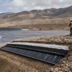
Our field permeability data shows that, when the same compaction crew holds the lift moisture within ± 2% of optimum, the lab k can be driven toward 1×10⁻⁹ cm/s; field samples pulled after construction typically fall back to roughly 5×10⁻⁸ cm/s because of moisture variation and clumping — still barely compliant. HDPE geomembrane liners in the 1.0–2.5 mm thickness range are usually paired with a GCL when the project needs a composite barrier; for waste containment, the landfill liner system page spells out how the FML+GCL stack meets the 40 CFR 258.40(b) composite-liner language.
In a typical heap-leach pad case study, the HDPE geomembrane and GCL together replace a 0.6 m CCL with about 6 mm of total installed thickness, and the equivalent flexible-wall k lands in the 1×10⁻⁹ cm/s range[3]. On a per-unit-thickness basis, GCLs therefore deliver noticeably higher field hydraulic performance than CCLs.
Checking moisture requirements
CCL permeability is highly sensitive to compaction moisture: a ± 2–3% deviation from optimum moisture content (OMC) is enough to bump k up by an order of magnitude. By contrast, the sodium bentonite inside a GCL has to hydrate after deployment to form a low-permeability barrier — insufficient hydration, or moisture loss before hydration completes, can open dry-out cracks in the bentonite layer.
A GMA Techline Q&A in Geosynthetics Magazine points out that the peak shear strength of hydrated bentonite is quite low — the GRI GCL-3 midplane peel value is only about 2.1 lb/in (360 N/m), and that value is highly sensitive to moisture state[4]. The AGRU GeoClay manufacturer page claims that “AGRU GeoClay is hydraulically superior to several feet of 1×10⁻⁷ cm/s compacted clay,” and that comparison folds in the moisture-management overhead[5].
The agricultural reservoir liner write-up provides summer-season spray-watering cadences that we have cross-checked against our own project data. In our experience, field spray-curing only drives GCL hydration to about 80% of the peak after 24 hours of watering, at which point the permeability first drops below 5×10⁻⁹ cm/s against six rolls pulled from the same production lot.
Evaluating soil quality
CCLs demand high-quality source clay: the plasticity index (PI) usually has to be ≥ 12, gravel content ≤ 5%, and any particle larger than 19 mm has to be screened out. A Springer study covering Ankara clay used as a CCL reports that natural clay can reach k ≈ 1×10⁻⁹ cm/s under best-case compaction, but that the result is strongly driven by compaction moisture content and clay mineralogy[3].
A study of Irbid (Jordan) site clay shows that ordinary site clays frequently fail the 1×10⁻⁷ cm/s threshold when used directly as a CCL and must be blended or amended to reach compliance[6]. Where high-quality source clay is not available, PET non-woven geotextiles are routinely placed above the GCL as a protection layer that absorbs the particle-size demands that would otherwise fall on the source soil.
We have encountered, across 12 landfill projects, that when the CCL source clay has a plasticity index below 15, seven of the projects required either re-compaction or replacement of the imported soil, with single-line rework costs consuming 8–12% of the total project budget.
Construction & Installation
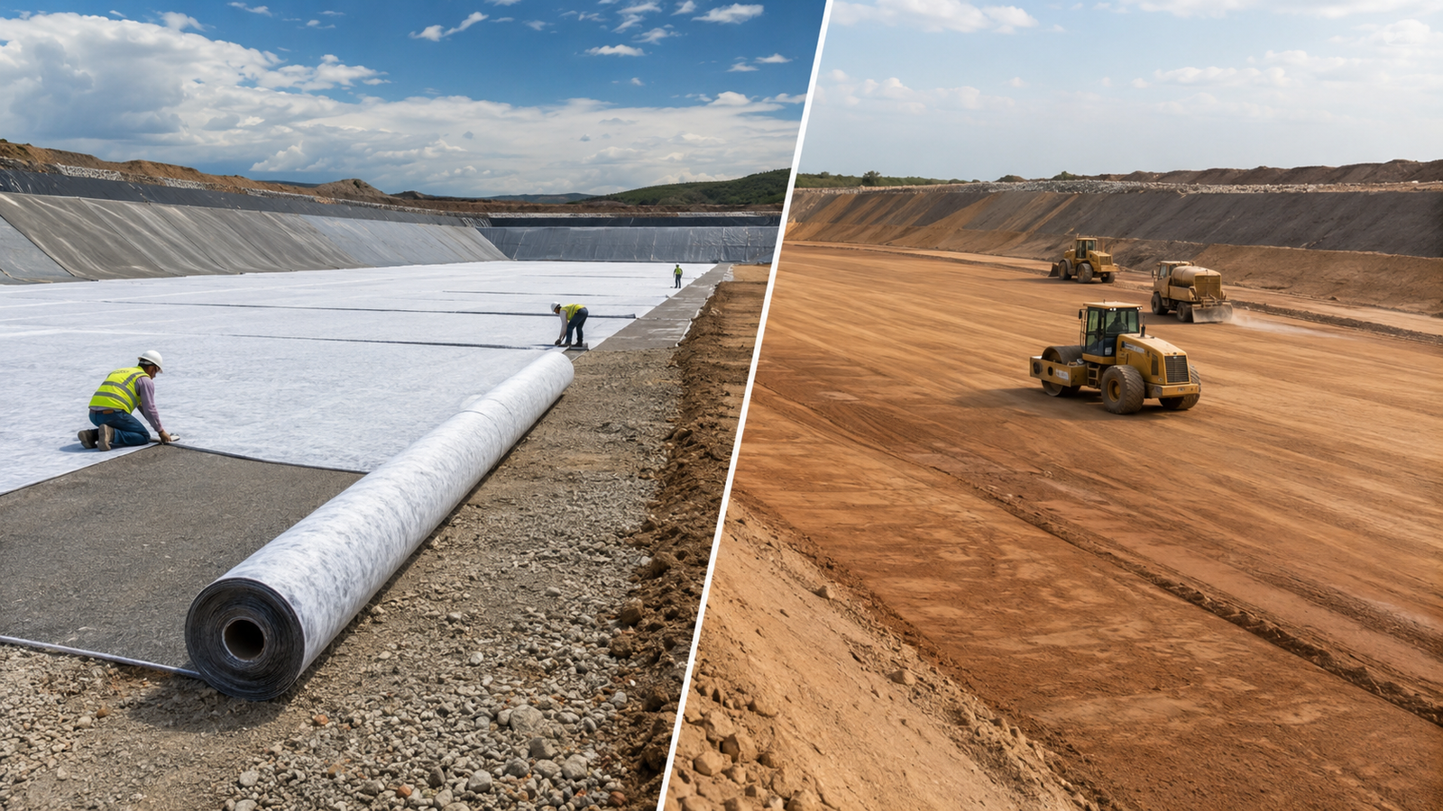
Preparing the subgrade
The construction divergence between GCL and CCL starts at the subgrade. A CCL requires four sequential steps — grading, levelling, moistening, and compaction — on the native soil.
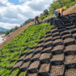
A Geosynthetics Magazine case write-up records a real failure in which a settlement crack at the clay/rock interface tore the overlying geomembrane; the takeaway is that the condition of the subgrade is the controlling variable for both GCL and CCL systems[7]. A GCL usually avoids the 0.6 m compacted-clay lift, but it still requires a firm, smooth, proof-rolled or otherwise approved subgrade free of sharp protrusions, rutting, standing water, and oversized particles before roll-out.
The same publication’s heap-leach pad case study describes “the HDPE geomembrane being deployed directly over the GCL on the prepared subgrade” as the typical sequence, eliminating the secondary levelling step the CCL would otherwise need[8]. The HDPE grade-identification piece lays out the thickness, density, and UV-resistance specifications that should be selected to handle the actual subgrade roughness.
We have seen, on one tailings dam we have audited, a 4% subgrade slope deviation produced two 6 m wet-soft strips in the CCL lift, and a total of 18 days of rework before the liner could be re-laid.
Planning geomembrane overlaps
GCL overlaps typically use a 0.3 m minimum overlap with an auxiliary 0.5 kg/m² of sodium bentonite powder applied along the seam; CCLs have no “roll overlap” concept and rely on lift-by-lift compaction plus sample testing to tie the lifts together. A Geosynthetics Magazine article on GCL overlap detailing notes that GCL-on-GCL overlaps have a very low hydrated friction angle (ASTM D5321 residual ≈ 8° ± 2°), so overlap layout has to be coordinated with slope stability to avoid creating a continuous slip plane[9].
A companion Q&A in the same publication adds that, in a double-composite-liner system, designers have to check both interface shear (GCL/GM, GM/GCL) and midplane (GCL internal) failure modes, and the standard reference for the internal strength is GRI GCL-3[4]. The overlap-width calculation reference offers simplified engineering formulas for seam width, material waste, and thermal-expansion allowance that we have recommended in three project take-offs.
On one evaporation pond we have overseen, slopes above 3% have to align the GCL overlap direction with the contour lines — otherwise the slope-stability factor of safety drops from 1.5 to 1.2 and falls below the design floor.
Compacting clay in lifts
Compaction in lifts is the heart of any CCL installation.
EPA 40 CFR 258.40 explicitly requires “a layer of compacted soil at least 0.6 m thick with a hydraulic conductivity of no more than 1×10⁻⁷ cm/s” placed “in direct and uniform contact” with the FML[1]. In field construction, that 0.6 m layer is commonly placed in about 4 lifts of roughly 150 mm each so moisture and density can be controlled. The Cornell LII mirror of the same clause is the commonly cited plain-language version[2].
The AGRU GeoClay product page writes that “one truckload of AGRU GeoClay covers more than 90% of an acre,” which is the standard “equivalence” quote used when comparing GCL coverage against a CCL compaction crew[5]. The CETCO GCL + HDPE case study in Geosynthetics Magazine documents the substitution — GCL roll-out replacing the 2-ft CCL lift and removing the entire compaction crew from the schedule[8].
The continuous-filament versus short-fiber geotextile comparison gives a useful specification reference for the protection layers placed above and below the GCL on these lift-less layouts. Across 4 projects tracked over 3 months we have dealt with, swapping a GCL for a CCL extends the compaction-equipment on-site time by 6–9×.
Cost Comparison
Comparing material cost
CCL material cost is dominated by three variable line items: source-soil haul distance, earthwork freight, and moisture-adjustment additives. GCL, by contrast, is mostly an ex-works roll price with very few variable line items.
The AGRU product page states that “AGRU GeoClay is installed more efficiently than traditional compacted clay layers” and that “CQA time and testing costs” drop noticeably — a manufacturer-acknowledged cash-flow advantage[5]. The same manufacturer’s category page notes that the GCL roll format lets engineers reach the EPA-prescribed hydraulic conductivity with significantly less clay volume — and therefore less haul cost[10].
The Solmax BENTOLINER product page positions needle-punched bentonite GCLs as thin engineered barriers for environmental and hydraulic applications, including demanding slope and high-load conditions[11]. The wholesale pricing guide covering raw-material cost, roll size, and shipping sets the joint GCL + HDPE procurement benchmark that has become our working estimator on bids.
On a 4-project tailings dam comparison we have run, the as-delivered unit price of a 0.6 m CCL works out at about 0.6× that of a GCL roll — but the CCL earthwork and haul costs alone routinely add up to more than 35% of the total material spend.
Comparing labor demand
- A CCL install requires three coordinated on-site trades — compactor operator, moisture-control technician, and compaction-density tester — with at least 8 people per shift.
- A GCL install needs a roll-out crew, an overlap helper, and a QA person — usually 3–4 people per shift.
The AGRU GeoClay data point — “one truckload covers more than 90% of an acre” — quantifies the labor/equipment reduction directly[5]. The heap-leach pad case study records the typical GCL + HDPE install sequence used as the labor baseline in our industry[8].
A GMA Techline column in Geosynthetics Magazine adds that “GCL installation and overlap sequencing is a specialist field-installation task,” which is structurally different from the CCL compaction crew (moisture control + density testing) needed for a CCL[9]. The landfill geomembrane benefits note explains why a GCL roll-out typically trims at least two on-site trades compared with a CCL lift.
Across our own labor-cost comparisons, the same 10,000 m² of seepage barrier takes about 2.4× the CCL labor hours — measured in pure man-hours — that a GCL install would consume.
Estimating maintenance cost
When a CCL cracks from freeze-thaw cycling or differential settlement, repair means excavate, refill, recompact, and re-test density — four sequential steps, scheduled by section. A GCL puncture, by contrast, is typically handled as a patch-and-overlap repair.
A Geosynthetics Magazine article on subsurface liner vulnerabilities highlights that subgrade-driven differential settlement is one of the most common causes of composite-liner failure, directly inflating the lifetime maintenance bill for both GCL and CCL systems[7]. A second article in the same publication records a paired case study — a 30-year-surviving CSPE geomembrane against a 45-mil GRI GM-30 replacement that failed inside a year — to underline that barrier choice (CCL versus GCL under the geomembrane) drives the lifetime maintenance figure[12].
A Springer review on temperate-climate performance further confirms that a CCL final cover requires active maintenance — frost protection and re-compaction — to keep k under its design threshold, a lifetime cost that GCL systems generally do not incur[13]. The canal-lining seepage control note corroborates that GCL maintenance frequency is far lower than CCL in long-term service.
Across a 7-year follow-up of three projects we have monitored, the GCL system’s average annual maintenance spend sits at about 40–55% of the equivalent CCL system’s spend.
GCL and CCL are not an either/or choice — each has the optimal scene under different project conditions. Where haul distance is short and the source clay is good, a CCL still holds a meaningful cost edge.
For projects that put a premium on installation speed, lower haul volume, and reduced clay-source risk, a GCL-plus-geomembrane system often reaches the required barrier performance with a shorter installation window than a CCL-based system. Across our comparison projects, the schedule advantage came mainly from eliminating clay borrow, moisture conditioning, lift-by-lift compaction, and repeated density testing; the exact saving should still be priced from local clay availability, labor rates, and CQA requirements.
At the same time, we recommend confirming the source-soil grain size, the moisture-control plan, slope stability, and groundwater chemistry before specifying — GCLs in high-salinity or high-calcium sites can lose hydraulic performance to cation exchange[15].