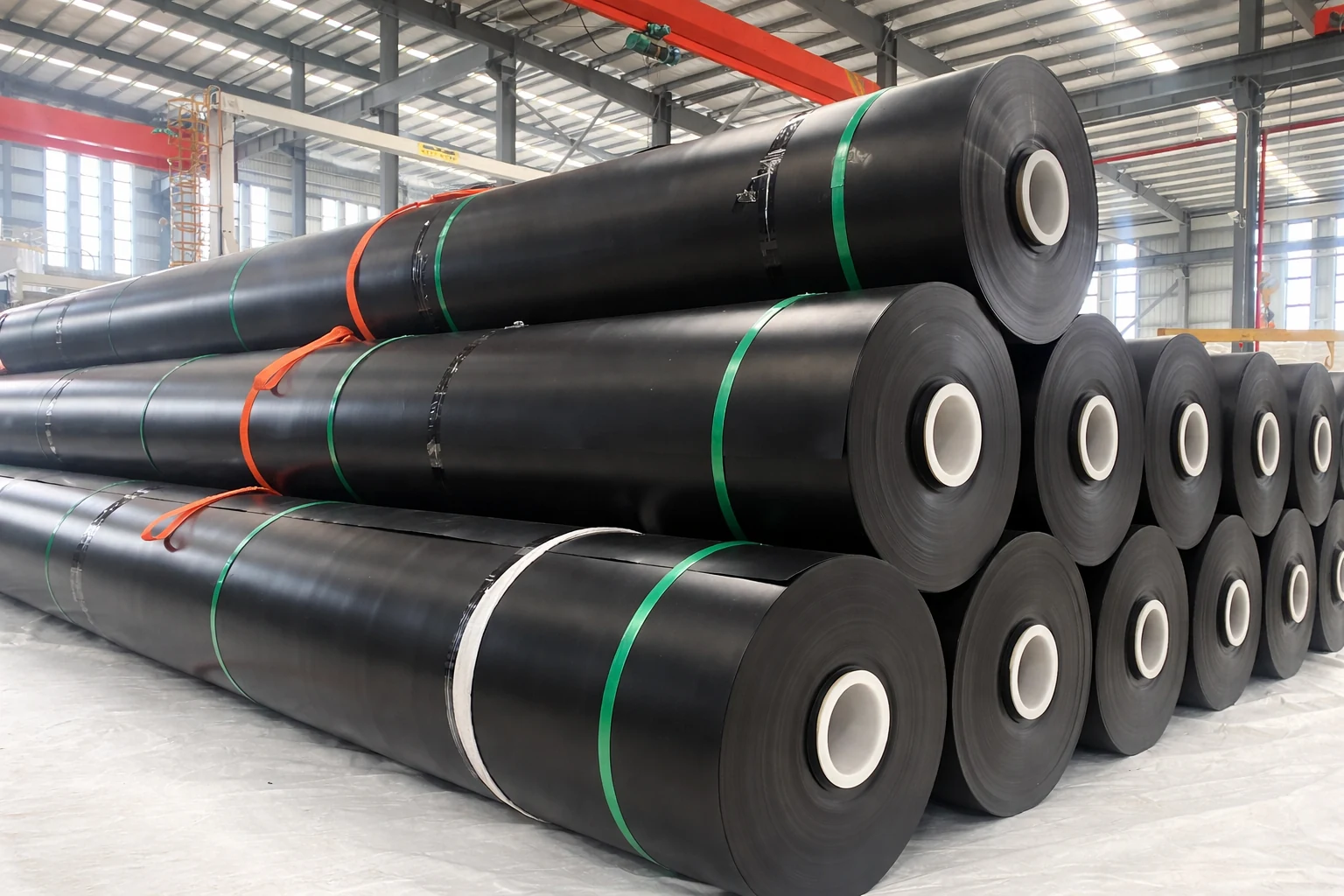
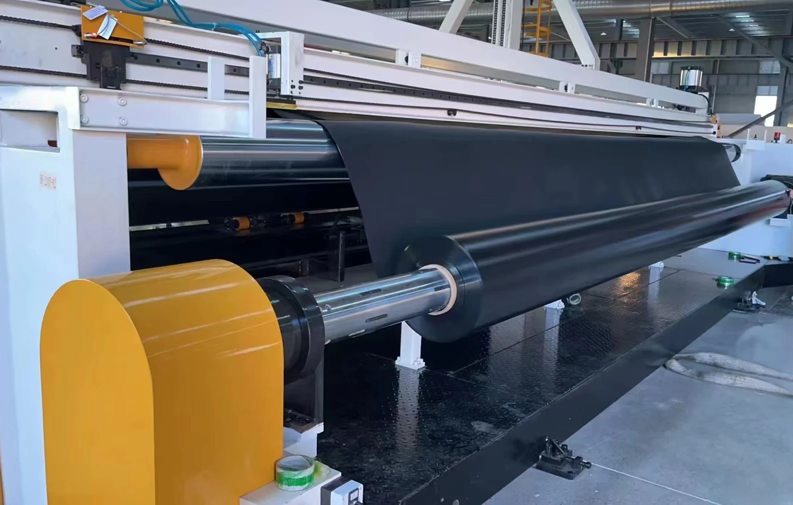
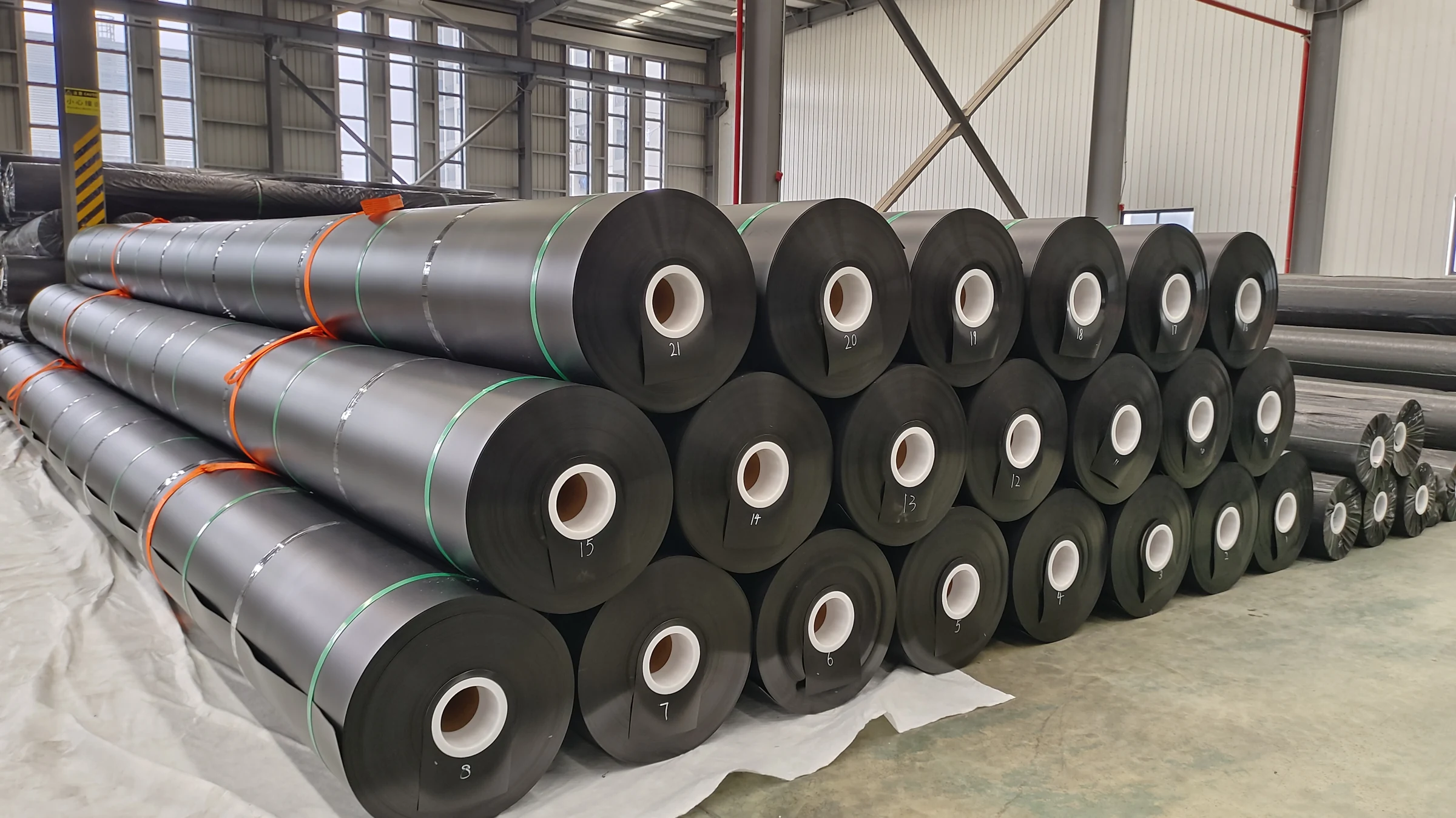
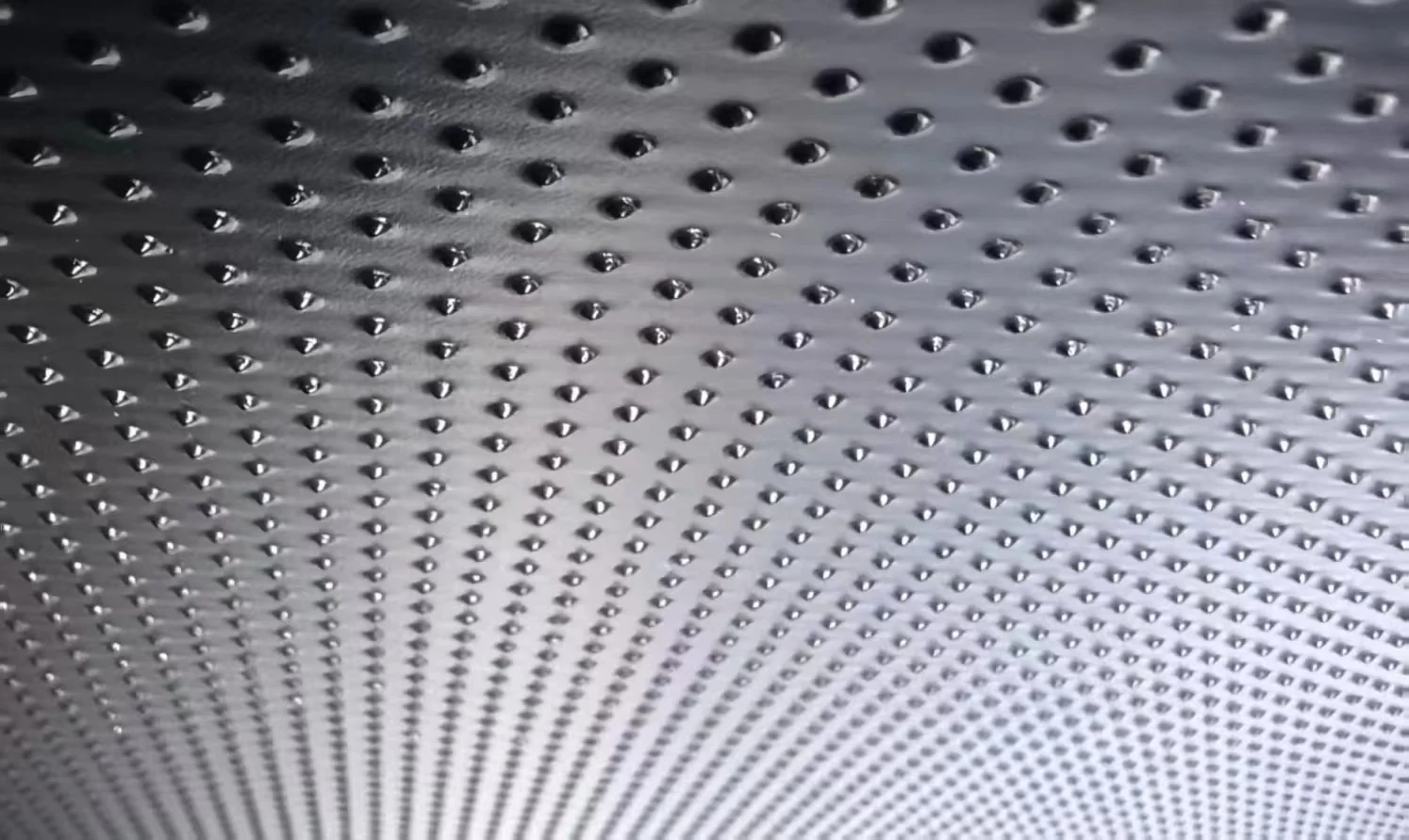
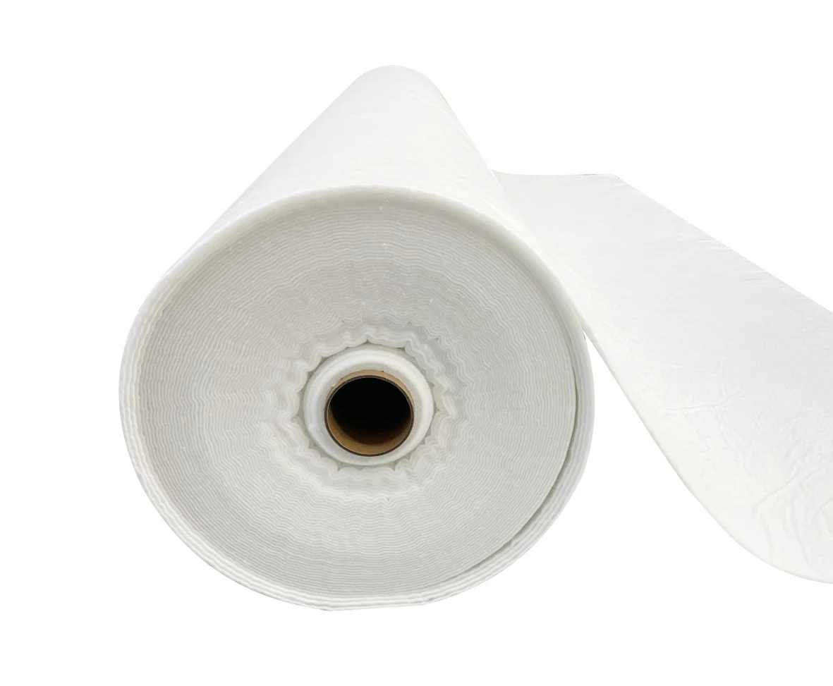

Jinseed runs GRI-GM13 material for its HDPE liner. Resin density starts at 0.940 g/ml, thickness is supplied in 7 steps between 30 mil and 120 mil, and rolls leave the plant at 8 m wide and about 1.6 t each.[1]
The two fail in different places. Membrane failure gathers at seams and puncture holes, while concrete failure gathers at contraction joints and cracks, and the two mechanisms need different detection tools, one working through a between-layer void and the other needing excavation before anything can be repaired.
Reclamation ran 34 test sections for 10 years, lost 7 of them, and measured seepage cuts of 70% to 95%.[2]
Covering 10,000 m² with 1.5 mm membrane takes 9 standard rolls of 8 m by 140 m, which comes to 14.2 t and fits one 40HQ container at 26 t. At 20,000 t of annual capacity the same 1.41 kg/m² gives about 14 million m² a year.
Concrete follows a different rulebook. US 40 CFR 258.40 sets the composite liner at 30 mil of membrane over 0.61 m of compacted soil with permeability below 1 × 10⁻⁷ cm/s. GB 16889 puts the clay underlay at 0.75 m.[3][4]
On price, the Reclamation sections ran from under USD 1.00/ft² to over USD 4.00/ft², or USD 10.8 to 43.1/m². Buried membrane is extrapolated to 50 to 100 years, and the best water-saving option returned a benefit/cost ratio of 3 to 4.1.[2]
Send the 4 numbers that fix a liner quote, thickness, roll width, order tonnage and destination port. You get back a container plan at 26 t per 40HQ box. Send the 4 numbers.
Material identity and specification basis
An HDPE liner is an extruded sheet. GM13 sets the working range at 30 mil to 120 mil, or 0.762 mm to 3.048 mm, and 60 mil equals 1.524 mm.[1]
Concrete is cast in place or placed as precast panels. Section thickness follows flow and cross-section, heavier sections take more reinforcement, and every panel joint needs a waterstop, a detail that decides how long the lining stays watertight once freeze and thaw starts working on the slabs.[5]
Self-weight separates the two by 2 orders of magnitude. A 1.5 mm sheet weighs 1.41 kg/m², a 100 mm slab weighs 240 kg/m², and the ratio is 170.
Tensile figures must be read in pairs. GM13 requires 22.1 kN/m at yield and 39.9 kN/m at break for 60 mil sheet, so the yield value is only 55% of the break value.[1]
Thickness tolerance is judged on the lowest of 10 readings. The plant holds ±3%, the specification allows −10%, and −10% puts the single-point floor for 60 mil at 1.37 mm.[1]
| Item | Membrane | Concrete lining |
|---|---|---|
| Form | Extruded sheet, welded into a continuous layer | Rigid cast-in-place or precast panels |
| Thickness | 30 mil to 120 mil, or 0.75 mm to 3.0 mm, in 7 steps | Governed by flow and section, joints between panels |
| Weight per m² | 1.41 kg/m² at 1.5 mm sheet | 240 kg/m² at 100 mm slab |
| Tensile reporting | Yield and break listed apart, 22.1 and 39.9 kN/m at 60 mil | Controlled by concrete grade and reinforcement |
| Joint type | Thermal welding, testable for air pressure and peel | Construction and expansion joints, waterstop required |
| Flexibility | Follows subgrade settlement, allowable strain about 3% | Rigid, cracks under differential settlement |
LLDPE liner grades sit in the same polymer family. It starts at 0.5 mm, stretches 800% at break against 700% for HDPE, and suits uneven sections or ground that settles.[6]
How seepage control differs
Seepage takes 2 routes. Pore flow passes through soil and clay liners, while discrete openings cover cracks in concrete panels, defective panel joints and holes in membrane. The clay threshold is fixed at 1 × 10⁻⁷ cm/s, and membrane blocks water with 0.75 mm to 3.0 mm of solid sheet.[7][4]
US rules for municipal solid waste landfills state the composite liner as hard numbers, and both components have to clear a threshold, so a designer cannot trade membrane thickness against soil thickness without changing the whole design basis.[3]
composite liner means a system consisting of two components; the upper component must consist of a minimum 30-mil flexible membrane liner (FML), and the lower component must consist of at least a two-foot layer of compacted soil with a hydraulic conductivity of no more than 1 × 10⁻⁷ cm/sec.
FML components consisting of high density polyethylene (HDPE) shall be at least 60-mil thick.
In metric, 30 mil is 0.762 mm and 60 mil is 1.524 mm. Two feet of compacted soil is 0.61 m, and the permeability threshold of 1 × 10⁻⁷ cm/s converts to 1 × 10⁻⁹ m/s.
Hazardous waste steps up one level to 2 liners with a leak detection layer between them, and the lower compacted soil grows from 0.61 m to 3 ft, or 91 cm.[8]
The leachate collection and removal system between the liners … is also a leak detection system. … (i) Constructed with a bottom slope of one percent or more; (ii) Constructed of granular drainage materials with a hydraulic conductivity of 1 × 10⁻² cm/sec or more and a thickness of 12 inches (30.5 cm) or more; or constructed of synthetic or geonet drainage materials with a transmissivity of 3 × 10⁻⁵ m2/sec or more.
That detection layer belongs to membrane systems alone. A 1% floor slope, a 12 in granular layer at 1 × 10⁻² cm/s, or a geonet at 3 × 10⁻⁵ m²/s lets a leak be traced through the void.
The granular figure converts to 1 × 10⁻⁴ m/s, some 5 orders of magnitude above the compacted soil threshold.[8]
Chinese rules share the logic and split the cases finer. Natural clay works when the base layer sits below 1 × 10⁻⁷ cm/s and is at least 2 m thick. Below that the project moves to a synthetic liner, and the clay underlay still has to reach 0.75 m at the same permeability.[4]
Where the base layer fails both tests, 2 synthetic liners become mandatory, with a drainage and detection layer between them, and leachate depth over the liner capped at 30 cm.[4]
Membrane carries the continuous barrier function. GM13 deliberately leaves water vapour transmission off its test list, because the value tells nothing about routine manufacturing control.[1]
Concrete joints are the weak point, and every contraction joint has to take a waterstop. Spacing errors lift the slab, and the leak path along one full joint exceeds what a single hole in a membrane would pass.[5]
A concrete cover over membrane moves the cracks to the other side. GM13 asks 108 lb, or 480 N, of puncture resistance from 60 mil sheet, and a sharp crack edge eats into that margin.[1]
| Item | Membrane | Concrete lining |
|---|---|---|
| Main leak path | Seam defects, puncture holes, poor connections | Contraction joints, cracks, failed joint sealant |
| Defect shape | Tiny area share, concentrated flow | Joint length sets effective permeability |
| Between-layer detection | Leaks can be located once a detection layer is installed | No interlayer void, leaks mean excavation |
| Repair route | Local patching, electrical survey finds the spot first | Recasting or grouting the failed panel, heavier works |
| Code requirement | 30 mil minimum, 60 mil for HDPE | Waterstop in every contraction joint |
| Risk in combined build | Punctured by sharp edges of a cracked cover | Loses its barrier function once cracked |
Membrane has one more advantage, because defects can be hunted down. An electrical survey still finds leaks once 0.3 m of water or 0.5 m of soil sits on top.
Cost structure and whole-life accounting
Reclamation placed 34 test sections across 4 states. Each covered about 30,000 ft², or 2,787 m², was watched for 1 to 10 years, and one section takes just 3 rolls of 1.5 mm sheet.[2]
Unit construction cost landed between under USD 1.00/ft² and over USD 4.00/ft², which converts at 1 ft² to 0.0929 m² into USD 10.8 to 43.1/m².[2]
The sections split into 4 families, exposed membrane, fluid-applied coating, membrane under concrete cover and concrete alone. Ponding tests before and after construction recorded seepage cuts of 70% to 95%.[2]
Seven of the 34 sections failed inside 10 years, or 21%, the rest stayed fair to excellent, and the best liner option returned a benefit/cost ratio of 3 to 4.1.[2]
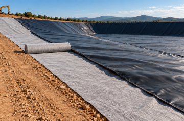
Membrane maths stays linear with the specification. One roll of 1.5 mm sheet at 8 m by 140 m holds 1,120 m² and weighs 1.58 t, so 10,000 m² takes 9 rolls and 14.2 t inside one 40HQ box at 26 t.
Scaling to 50,000 m² gives 45 rolls and 71 t across 3 boxes.
Trial orders from 1 t, standard rolls in 7 to 15 days
Concrete carries more cost lines. A 100 mm section adds reinforcement or wire mesh, formwork, curing, saw cutting and joint sealant on top of the concrete volume, and formwork is amortised over 3 to 5 uses.
Volume tells the same story. A 100 mm slab uses 0.1 m³ of concrete per m², or about 0.24 t, so 10,000 m² takes 1,000 m³ and 2,400 t. The same area in 1.5 mm membrane comes to 14.1 t, one 40HQ box against 92 boxes for concrete.
Lining can push an irrigation canal budget up by as much as 50%, and squeezed projects often line only the reaches where the base layer sits above 1 × 10⁻⁵ cm/s.[7][4]
Lost head rarely gets counted, and that omission flatters every concrete option. A hydroelectric canal runs a few km, an irrigation canal runs past 100 km, and 1 m³/s of leakage adds up to roughly 31.5 million m³ a year.[7]
| Metric | Value | Basis |
|---|---|---|
| Test sections | 34, across 4 states | Reclamation 10-year report |
| Section area | About 30,000 ft², or 2,787 m² | Reclamation 10-year report |
| Unit construction cost | Under USD 1.00 to over USD 4.00/ft² | Reclamation 10-year report |
| Metric unit cost | USD 10.8 to 43.1/m² | Calculated at 0.0929 m² per ft² |
| Seepage reduction | 70% to 95% | Ponding tests before and after |
| Benefit/cost ratio | 3 to 4.1 | Water saved against money spent |
| Sections failed in 10 years | 7 of 34, or 21% | Reclamation 10-year report |
| Lining share of canal cost | Up to 50% | Irrigation canal basis |
Installation sequence and programme
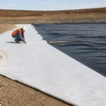
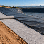
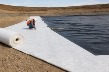
Membrane wins on step count. A roll arrives, gets unrolled, overlapped, welded and electrically surveyed for leaks. No curing wait applies, and standard material ships in 7 to 15 days against 7 to 28 days of concrete curing that blocks water.
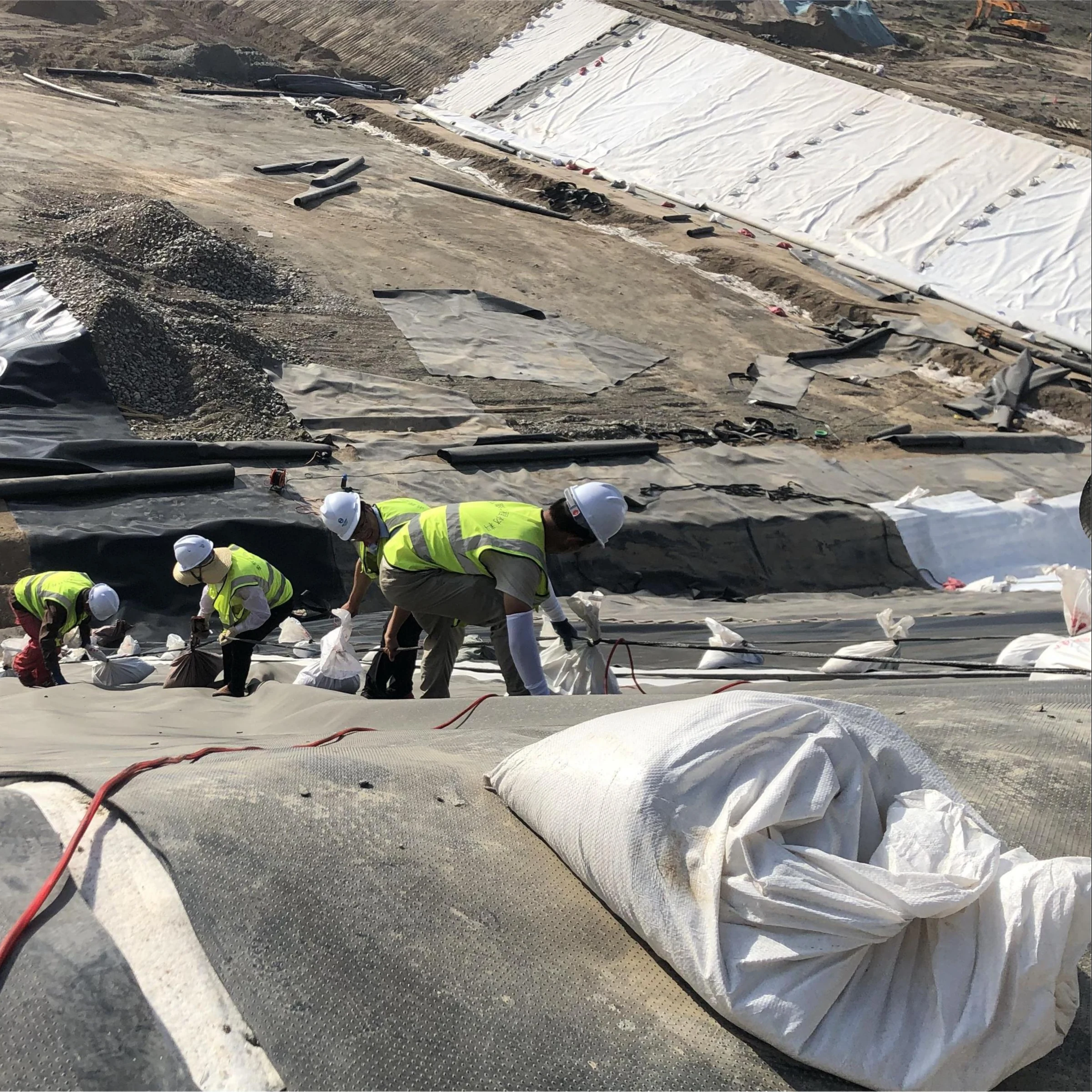
Three field controls decide membrane quality. Subgrade compaction stays above 90%, overlap runs 100 mm to 150 mm, and a dual-track wedge weld passes an air test at 0.25 MPa held for 5 minutes with no drop.
A trial weld anchors the parameters. Crews weld a 1 m length first for peel and shear, take 16 kN/m as the reference peel strength for HDPE, and only then start production seams.
Wider rolls cut the waste factor. An 8 m roll carries two to three tenths fewer seams than a 5.8 m roll, and allowing 100 mm to 150 mm overlap plus 1.05 to 1.10 for slopes and anchor trenches leaves a net 1,106 m² per roll.
Anchorage in a trench is optional. The Toshka main canal in Egypt stands 7.5 m high on 2 to 1 slopes, skipped the trench because cover followed the welds closely, and saved 700,000 m² of membrane, 3.5% of the 20 million m² used on the job.[7]
Thermal movement needs handling before it starts. The sheet has a high expansion coefficient and only 0.2 to 0.5 of interface friction, so smooth face down is the worst orientation for wrinkles, and a controlled placement window with slack in the sheet keeps them down.[7]
Wrinkles break the next trade. A high wrinkle makes panel-to-panel welding harder and stops a 0.1 m cast cover from bedding down, and 1.41 kg/m² of self-weight will not press it flat.[7]
Anchorage is designed in two directions, along the canal and across it. Crest anchor trenches are standard practice, and at a longitudinal slope of 0.1 m/km, or 1 × 10⁻⁴, the sliding margin is wide.[7]
Depth of cover follows heat transfer. Holding a 30 °C surface swing down to 1 °C at the membrane takes 0.15 m for a 1 hour exposure and 0.5 m for a 1 day exposure.[7]
Groundwater is the separate risk. Once the water table sits 0.5 m above the canal level the sheet lifts, and self-weight is 3 orders of magnitude short of the head difference.[7]
Acceptance points in the installation sequence
- Subgrade compaction reaches 90% before sharp objects are cleared.
- A needle-punched non-woven geotextile of 400 g/m² or more covers stones and crack edges.[7]
- The membrane is unrolled inside the temperature window with slack left in the sheet.
- A dual-track wedge weld holds overlap between 100 mm and 150 mm after a trial weld each shift.
- The seam passes an air test at 0.25 MPa for 5 minutes with no pressure drop, with peel and shear added where needed.
- An anchor trench or ballast goes in, checked separately for uplift and for downstream displacement.
- A 400 g/m² non-woven separation layer sits under the cover so no sharp edge touches the sheet.
Seam records and trial weld data ship with each roll, so your inspector works from the same numbers. Read the welding control points.
Durability and service-life conventions
Three index groups lock durability, and each one is checked on a different timescale. GM13 asks 100 min of standard OIT and 400 min of high-pressure OIT, with carbon black between 2.0% and 3.0%.[1]
After 90 days in an 85 °C oven, standard OIT has to retain 55% and high-pressure OIT 80%.[1]
Stress crack resistance has its own bar. GM13 refers to the 2 hour notched constant tensile load test in GRI-GM10 and asks 500 h, while the plant runs the same method past 2,000 h.
UV performance is read as retention. The fluorescence UV test runs to 1,600 h, the specification asks 50% retention on high-pressure OIT, and the plant holds above 60%.
Chemical resistance is quoted as a pH band. The plant works from pH 1 to 13, or 0.1 mol/L to 1 × 10⁻¹³ mol/L of hydrogen ions, and anything outside needs a compatibility test before the grade is fixed.[1]
Temperature sets which service life applies. Buried conditions extrapolate by Arrhenius modelling to 50 to 100 years, while exposed conditions carry a heavier UV and thermal load.
A 1.5 mm sheet absorbs frost heave through 700% elongation at break, whereas a concrete cover or cast lining is rigid enough to be pulled apart by repeated freeze and thaw.[7][1]
Concrete fails at the joints, while the slab itself holds. The sealant ages first, and once a joint opens the whole layer stops being a barrier, so plain concrete canals run an inspection cycle of 5 to 10 years.[5]
Engineering applications
Landfill base liner is the most standardised use. The composite liner package starts at 30 mil of membrane over 0.61 m of compacted soil, the membrane goes to 60 mil, and the leachate collection layer holds liquid under 30 cm deep.[3]
Chinese landfill rules split the same way. Below 1 × 10⁻⁷ cm/s at 2 m of base thickness, natural clay is enough, and anything short of that moves up to a single or double synthetic liner.[4]
Heap leach pads carry heavier loads. Ore stack pressure, acidic lixiviant and long slope shear arrive together, so 2.0 mm sheet or thicker with a textured face is usual, and interface friction can reach 30° on 2 to 1 slopes.
New canals and reservoirs must be lined. Both routes sit inside Reclamation standards, a 1.5 mm membrane under a concrete cover or a plain concrete lining.[5]
A 100 km canal with an 8 m lining width covers 800,000 m². That takes 714 rolls and about 1,129 t of 1.5 mm membrane, or 44 containers, against 80,000 m³ and 192,000 t for a 100 mm concrete slab over the same area.
Concrete holds its ground at high velocity. A concrete lining tolerates about 6 to 7 m/s, a concrete-filled geomattress 5 to 7 m/s, and a plain geomat only 1 m/s.[7]
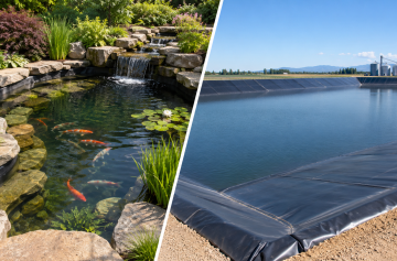
Aquaculture ponds run LLDPE from 0.5 mm upwards, and the more flexible grades suit walls that settle.[6]
Tunnels and roadbeds use membrane to solve headroom and load. Adding 1.5 mm sheet lifts the dead load by 141 kg per 100 m².
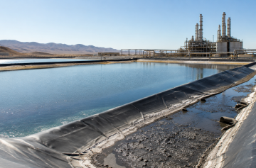
Leachate lagoons and evaporation ponds behave the same way. Corrosivity varies widely, and a pH outside 1 to 13 calls for a different grade or a protective layer.
Combining the two materials
A membrane supplies the barrier and a 0.1 m concrete cover supplies mechanical protection. On a 1.5 to 1 slope the worked example returns a sliding safety factor of 349, and the membrane against concrete comparison follows an allowable velocity of 6 to 7 m/s.[7]
The cover list runs long. It blocks animals, boats, floating debris, floating ice, falling objects and hail, resists abrasion by suspended particles, absorbs thermal movement and shields the sheet from solar radiation.[7]
The combination needs a separation layer. A needle-punched PET non-woven geotextile of 400 g/m² or more between sheet and cover handles stones, panel corners and crack edges at once.[7]
That same depth controls temperature. Soil at 0.15 m cuts a 1 hour swing of 30 °C to 1 °C, and 0.5 m does the same for a 1 day swing.
An existing cracked concrete canal can be relined directly, with the old surface acting as cushion and membrane thickness raised from 1.5 mm to 2.0 mm.[7]
Tell us the lining area, the subgrade and the flow velocity. We answer with a 1.0 to 3.0 mm thickness recommendation, a panel layout and a container count for your port. See how batches are released Request the liner quote
Selection logic and common mistakes
Sorting the two materials by duty clears the decision. Membrane leads on low-velocity canals and reservoirs, landfill and hazardous waste liners, heap leach pads and tailings, aquaculture ponds, secondary containment and evaporation ponds, plus relining old concrete canals at 1.0 mm to 2.0 mm.
Concrete leads above 6 to 7 m/s, with abrasive sediment, on navigable water, with floating debris and ice impact, or where 240 kg/m² of self-weight is needed against uplift.[7]
Reading yield and break tensile as one figure is the first mistake, since GM13 lists them as separate properties.[1]
The second is mixing mil and mm. One mil is 0.0254 mm, so 1.5 mm measures about 59 mil and is not the exact equal of 60 mil, which means a document should stay in one unit.
The third is assuming concrete is watertight. Codes still require a waterstop in every contraction joint, a 0.1 m cover still cracks, and the barrier is only as good as the joint.[5]
Groundwater is the variable that gets missed. Once the water table sits 0.5 m above canal level the sheet lifts, and a head difference of 0.5 m puts 4.9 kN on each m² against 0.014 kN of membrane self-weight, a ratio near 350, so ballast or drainage belongs in selection.[7]
Procurement and acceptance points
Product type, thickness or grammage, roll format, order quantity, destination port and end use make up the 6 inputs a quote needs to land first time. A drawing or tender requirement saves a further round, and the cost drivers are thickness, roll format, freight and installation.
Trial volume starts at 1 to 3 t. Export shipments should reach one 40HQ box at 76 m³ and 26 t, standard material ships in 7 to 15 days, and custom, mixed or peak-season orders take 15 to 25 days.
Acceptance runs batch by batch, with thickness, OIT, carbon black and stress crack resistance checked on every release, and third-party witnessing available through BTTG or TRI Environmental.
Seam records belong with the project file. Measured overlap between 100 mm and 150 mm, air test pressure and hold time, and trial weld parameters are logged so a later leak survey has a baseline.
Sources of data
Figures here come in 3 layers. Official and published material is the first layer, covering the GRI GM13 and GM17 specifications, US 40 CFR 258.40 and 264.301, GB 16889-2008, the Reclamation 10-year report and the canal lining design paper by Giroud and co-authors, all marked at the sentence.
The second layer is common industry practice without a source. It covers subgrade compaction at 90%, overlap of 100 mm to 150 mm and air testing at 0.25 MPa for 5 minutes.
Concrete curing runs 7 to 28 days, formwork is amortised over 3 to 5 uses, and plain concrete canals are inspected every 5 to 10 years.
Electrical leak location still works under 0.3 m of water or 0.5 m of soil, and textured membrane friction reaches 30° on 2 to 1 slopes.
The third layer is manufacturer data and calculated values. Jinseed figures include thickness tolerance of ±3%, stress crack resistance past 2,000 h and high-pressure OIT above 600 min.
Carbon black runs from 2.0% to 3.0%, UV exposure for 1,600 h leaves OIT retention above 60%, and buried design life is quoted at 50 to 100 years, with the 2,000 h and 600 min values above the GM13 bars of 500 h and 400 min.
Seven calculated values are listed with their working. Membrane at 0.94 g/cm³ gives 1.41 kg/m², a roll of 1,120 m² weighs 1.58 t, and 1 ft² equals 0.0929 m² for the unit price conversion.
One mil equals 0.0254 mm, which puts the sheet at about 59 mil, and a purchase quantity of 14.2 t runs 0.1 t above the theoretical 14.1 t because rolls are taken whole.
Finally, 240 kg/m² divided by 1.41 kg/m² gives the factor of 170, and 20,000 t of annual capacity divided by 1.41 kg/m² gives about 14 million m².
Sources
- Geosynthetic Institute. GRI Test Method GM13: Standard Specification for Test Methods, Test Properties and Testing Frequency for High Density Polyethylene (HDPE) Smooth and Textured Geomembranes. geosynthetic-institute.org
- U.S. Department of the Interior, Bureau of Reclamation. Canal-Lining Demonstration Project Year 10 Final Report (unit construction cost less than USD 1.00 to more than USD 4.00 per square foot, seepage reduction 70 to 95 percent, benefit/cost ratios of 3 to 4.1). www.usbr.gov
- U.S. Electronic Code of Federal Regulations. Title 40, Section 258.40: Design criteria for municipal solid waste landfill units. www.ecfr.gov
- Ministry of Ecology and Environment of the People’s Republic of China. GB 16889-2008 Standard for pollution control on the landfill site of municipal solid waste (liner classification, clay underlay of at least 0.75 m, natural base layer of at least 2 m, permeability below 1.0 x 10⁻⁷ cm/s, leachate depth over the liner not more than 30 cm) [in Chinese]. www.mee.gov.cn
- U.S. Department of the Interior, Bureau of Reclamation. Canal Operation and Maintenance: Embankments (lining of newly constructed canals, geomembrane under concrete). usbr.gov
- Geosynthetic Institute. GRI Test Method GM17: Standard Specification for Test Methods, Test Properties and Testing Frequency for Linear Low Density Polyethylene (LLDPE) Smooth and Textured Geomembranes. geosynthetic-institute.org
- Giroud J.P., Plusquellec H., Blond E. Design of canals lined with geomembranes. E3S Web of Conferences 368, 01001 (2023), indexed in FAO AGRIS. agris.fao.org
- U.S. Electronic Code of Federal Regulations. Title 40, Section 264.301: Design and operating requirements for hazardous waste landfills (double liner, 3-foot compacted soil at no more than 1 x 10⁻⁷ cm/sec, leak detection layer with 1 percent bottom slope). www.ecfr.gov